

Introduction
Materials and Methods
Overview and operation of the walking-type pepper transplanter under development
Rollover theory
Simulation and validation procedures
Results and Discussion
Evaluation of center of gravity coordinates
Lateral rollover characteristics
Longitudinal rollover characteristics
Conclusion
Introduction
In recent years, rollover accidents involving agricultural machinery have become a significant global safety concern, particularly in regions with uneven terrain and sloped upland fields (Watanabe and Sakai, 2019). Operating agricultural machinery on inclined or sloped terrain significantly increases the risk of instability, often resulting in lateral or longitudinal rollovers that can cause severe injury or death (Chowdhury et al., 2020; Song et al., 2021). In Republic of Korea, about 23% of farmland lies on slopes steeper than 8.5 degrees, elevating the risk of machinery rollover incidents. According to 2021 reports, a total of 44,302 agricultural machinery-related accidents were recorded, with 11,683 cases representing 26.37% involving lateral overturning and backward rollover incidents (Jang et al., 2022).
Among various types of agricultural machinery, walk-behind transplanters particularly those used for upland crops like red pepper are highly susceptible to rollover incidents due to their compact size, narrow tread width, and elevated center of gravity (CG), especially when operating on sloped terrains (Chowdhury et al., 2023). Although efforts have been made to automate pepper transplanting operations to reduce labor and improve efficiency, many designs have not adequately addressed safety aspects related to field stability, particularly when operating on sloped terrains (Iqbal et al., 2022).
To enhance safety in agricultural machinery operations, it is essential to integrate theoretical models, simulations, and experimental research aimed at improving design, training effectiveness, and safety standards (Yang et al., 2024). Theoretical models and simulations play a crucial role in predicting the stability and rollover behavior of agricultural machinery. These models are validated through field tests or testing platforms to ensure their accuracy in representing real-world conditions, thereby enabling the recommendation of safe operating limits (Carabin et al., 2025). Previous studies have identified critical design parameters such as wheelbase, track width, and CG height as key factors influencing rollover tendency Gebennini et al., 2008). To assess the farm machinery stability, researchers have developed various modelling and evaluation methods including axle-lift experiments, tilt table tests, and dynamic simulations using Newtonian and kineto-static approaches (Guzzomi, 2012). Carabin et al. (2025) conducted rollover stability simulations and experiments on a full-scale tractor using a tilting rotary rig. The lateral rollover angle decreased from 31.3 to 29.6° as the CG shifted rearward due to load variations. Changes in mass distribution between the front and rear axles, ranging from 39 to 61% and from 44 to 56%, influenced the stability of the tractor. Kim et al. (2022) utilized 3D simulations to evaluate the rollover angles of a self-propelled radish harvester under various load conditions. When the rollover angle reached 27 to 28°, the right wheel lost contact with the ground. However, adding 50 to 150 kg of weight to the front, center, or rear of the machine improved its stability, increasing the rollover angle to meet or exceed the 30° safety threshold.
Peppers are cultivated on extensive areas worldwide and ranks as the second most important vegetable crop after tomatoes (Devi et al., 2021). Global pepper production in 2022/2023 was approximately 520,000 t, which did not meet the estimated demand of 530,000 t (Nedspice, 2023). In Korea, the overall mechanization rate for pepper cultivation in 2022 was 48.3%; however, the transplanting process remained almost entirely manual, with a rate close to 0.0%. This level is markedly lower compared with other seasonal vegetables such as onion (66.3%) and garlic (61.8%), which recorded transplanting rates of 16.1% and 14.8%, respectively (RDA, 2023). The increasing demand for mechanized pepper transplanting in upland fields highlights the need for safety-evaluated machinery suitable for such farming conditions. This study employed a combination of simulation and inclination platform analytical approach to evaluate the rollover characteristics of a 3.4 kW walking-type pepper transplanter prototype under development stage. The objective was to determine the safe operating inclination that minimizes the risk of rollover during transplanting tasks, through simulations using a commercial software and validation tests using an inclination test platform.
Materials and Methods
Overview and operation of the walking-type pepper transplanter under development
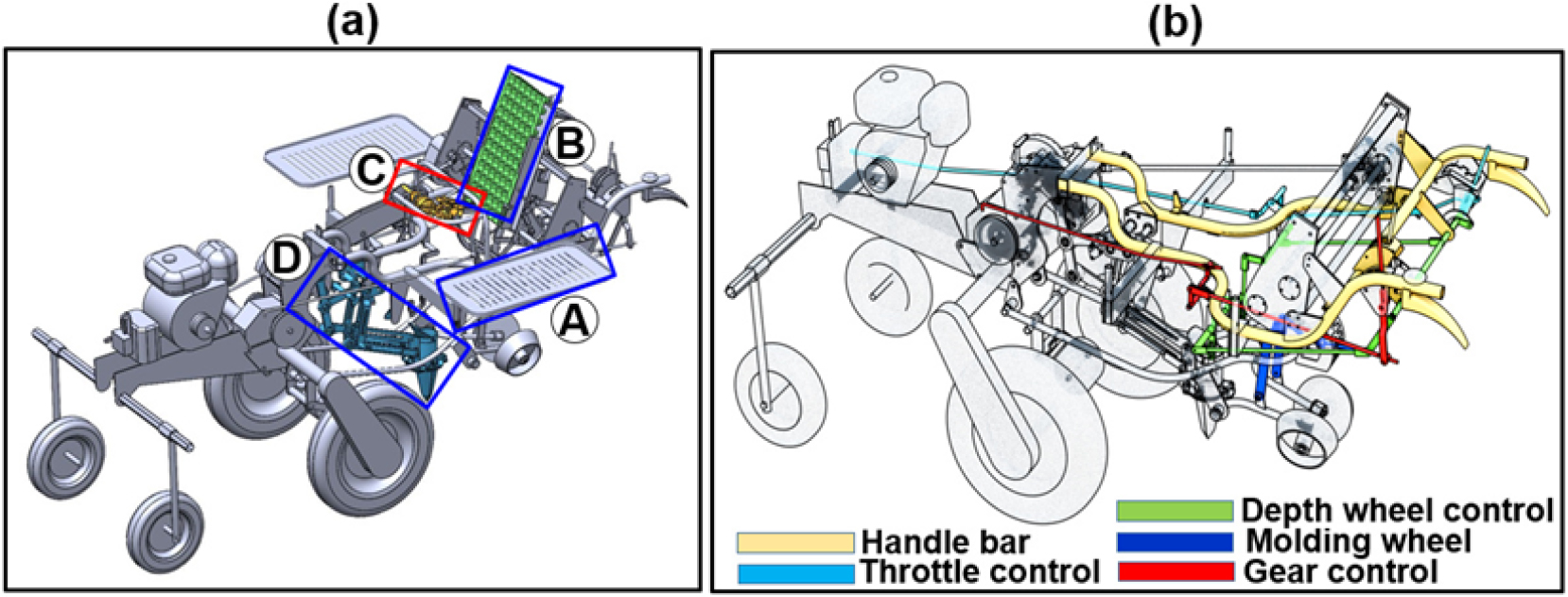
Fig. 1 illustrates a 3D model of a 3.4 kW walking-type pepper transplanter prototype developed for planting pepper seedlings in a single row. The operation process begins with engine startup, initiated by manually pulling the handle wire while adjusting the choke to regulate the fuel-air mixture during ignition (Eliezel and Hong, 2022). Once the engine is running steadily, the transplanting throttle lever is engaged, transmitting mechanical power from the engine to the transplanting components via a belt-driven system. The belt transfers rotational power to activate the operational mechanisms of the tray conveyor, seedling-picking component, and planting unit, ensuring their synchronization with the forward movement of the transplanter.
The operator walks behind the transplanter and manually steers it using the handlebar, which provides precise directional control and facilitates row alignment in the field. The handlebar components also feature a throttle control lever, enabling the operator to adjust the engine speed and thereby control both the forward speed and the transplanting process. As the transplanter advances, seedlings are continuously picked from the tray cells, transferred to the planting hopper by the picking device, and inserted into the soil by the hopper of the planting unit. During seedling deposition into the soil, the planting depth is maintained by the depth wheel adjustment, and the molding wheel presses soil around the base of the seedling to ensure good contact with the root zone.
The operating characteristics of the walking-type pepper transplanter are significantly influenced by the CG and load mass distribution under realistic field conditions. To analyze the rollover characteristics, key geometric and physical parameters of a rigid body were extracted from the 3D CAD assembly and incorporated into the virtual environment of commercial simulation software. The modelling of the structural frame and major components including the front and rear wheels, planting unit, seedling tray holder, and power transmission mechanisms. For rollover analysis, symmetry was assumed along the central longitudinal axis, with the tires and support arms individually defined for the left- and right-side directional motion of the transplanter. Fig. 2 illustrates the configuration of the rigid body components, while Table 1 presents the corresponding dimensional specifications.
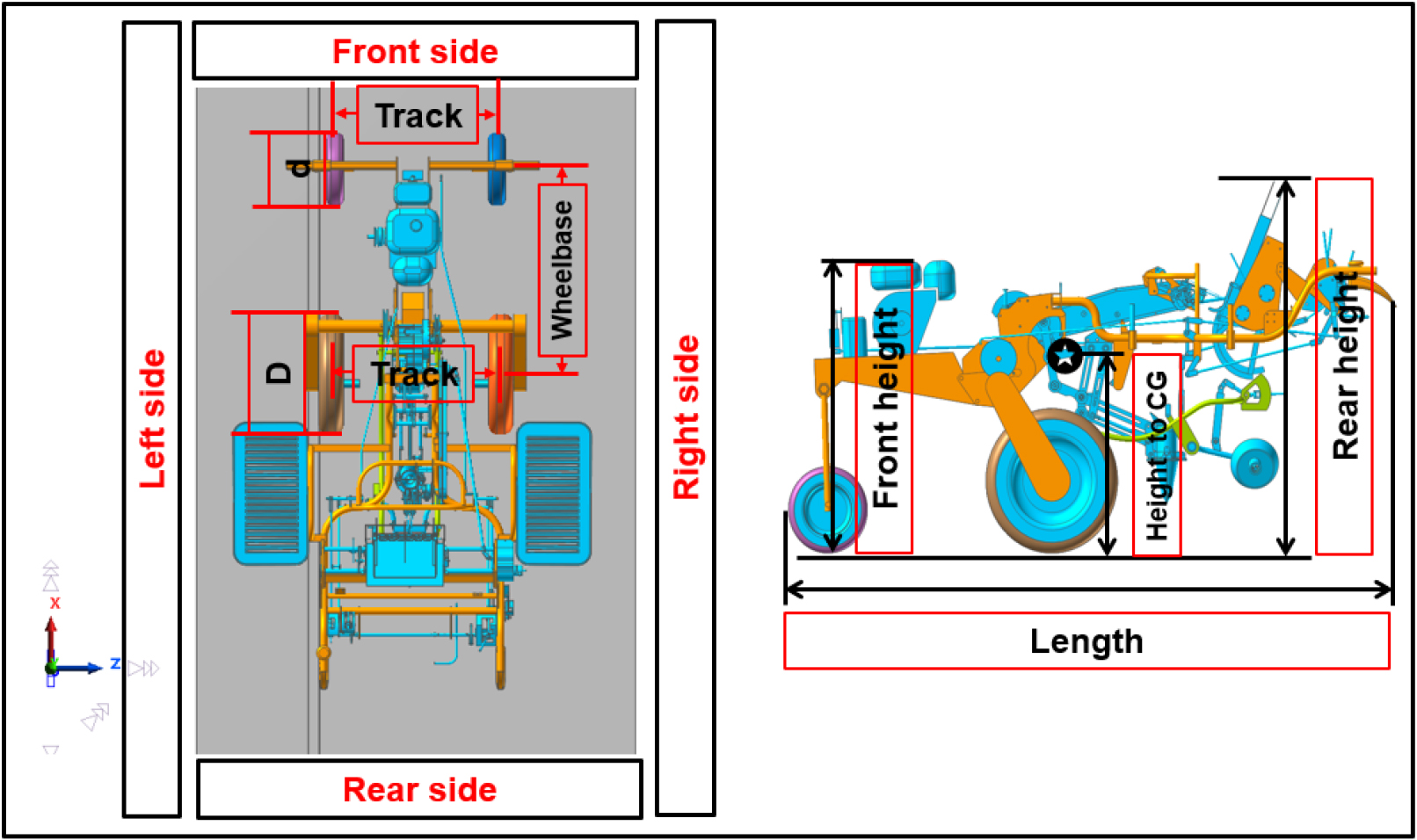
Table 1.
Dimensions of rigid model components (mm).
| Length | Height | Width | Front wheel diameter | Rear wheel diameter | Front track | Rear track | Wheelbase |
Height to CG |
| 2,260 | 1,410 | 1,370 | 328 | 549 | 737 | 771 | 934 | 766 |
Rollover theory
Lateral rollover
In mechanized seedling transplanting, the lateral rollover of the transplanter is a critical design consideration, especially when operating on uneven or sloped terrain, as it can result in rollovers, operator safety risks, and seedling damage. Evaluating the static rollover threshold using a center-of-gravity-based approach is crucial to understanding the lateral instability of the transplanter, which can result in rollovers to the left- and right-side directions (Kim et al., 2017). Mathematically, the CG, represent the unique point at which the weighted average of the component masses is considered to act with respect to a chosen reference coordinate system. The location of the CG plays a pivotal role in determining the lateral static stability of a transplanter, defined as the ability to resist tipping over during operation on sloped or uneven terrain. The CG can be calculated using Eq. (1):
Lateral rollover occurs when the overturning moment generated by the tangential component of gravitational force acting through the CG exceeds the restoring moment provided by the ground reaction forces at the wheel contact points. When the transplanter operates on a right-sloping surface (i.e., with the downhill direction toward the right side), the CG effectively shifts closer to the left wheel. This shift increases the horizontal distance from the CG to the tipping axis on the left side thereby elevating the risk of rollover in the leftward direction. Fig. 3 illustrates the representation of static rollover conditions.
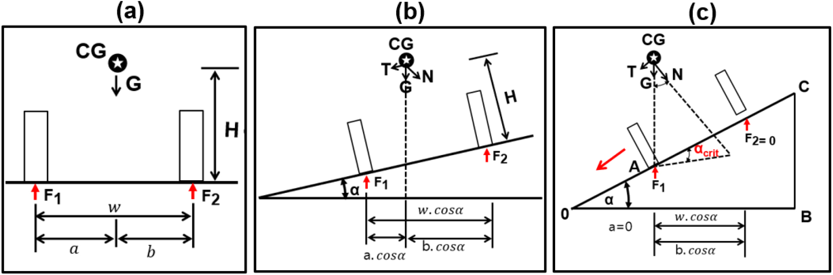
Fig. 3.
Representation of static rollover conditions: (a) free-body diagram on a flat surface, (b) free-body diagram on a sloped plane, and (c) free-body diagram at the critical stability condition. CG, center of gravity; G, gravitational force; N, normal reaction force (normal component of G); T, tangential (downslope) component of G; F1 and F2, ground reaction forces; α, slope angle; H, height; w, wheelbase; a and b, horizontal distances from the CG to the front and rear wheel contact points, respectively.
The rollover angle α defined as the maximum slope angle at which the transplanter remains in static equilibrium before tipping occurs, can be expressed as:
If the lateral distance b from the CG to the left wheel is relatively small, or the CG height H is large, the resulting rollover angle α decreases. This reduction in the rollover angle corresponds to a lower lateral stability margin, thereby increasing the susceptibility to tipping. In such cases, the transplanter becomes more prone to rollover when subjected to right-sloping terrain. Therefore, for left-side tipping, the greater the lateral offset of the CG toward the right side of the farm machinery, the higher the rollover risk due to the shortened moment arm resisting overturning (Kang et al., 2022).
Conversely, on a left-sloping surface, the system risks tipping over the right wheel. Here, the moment arm is a (distance from CG to right wheel), and the critical tipping angle can be expressed as:
If heavy loads are mounted on the left side, they shift the CG leftward, reducing a, and thus lowering α at right direction. This asymmetry implies that unbalanced designs with lateral mass offsets can create unequal rollover resistances in left and right directions. Such imbalance is especially important for pepper transplanters, which often operate in raised-bed conditions where one wheel may sit higher than the other, exacerbating the tipping moment (Lin et al., 2018).
Longitudinal rollover
Dynamic longitudinal rollover in agricultural machinery refers to the ability to resist tipping forward or backward during motion, particularly under conditions involving sloped terrain, turning, braking, or climbing (Zhilin et al., 2019). The dynamic rollover considers the effects of inertial forces, linear acceleration, and angular motion, all of which can significantly influence rollover thresholds and operational safety (Hung and Khanh, 2024). Rear and front rollover incidents typically occur during uphill acceleration and downhill braking, respectively. Based on the dynamic free-body diagram as shown in Fig. 4, a comprehensive mechanical analysis was conducted to derive expressions for the slope angles and angular velocity thresholds associated with rollover conditions.
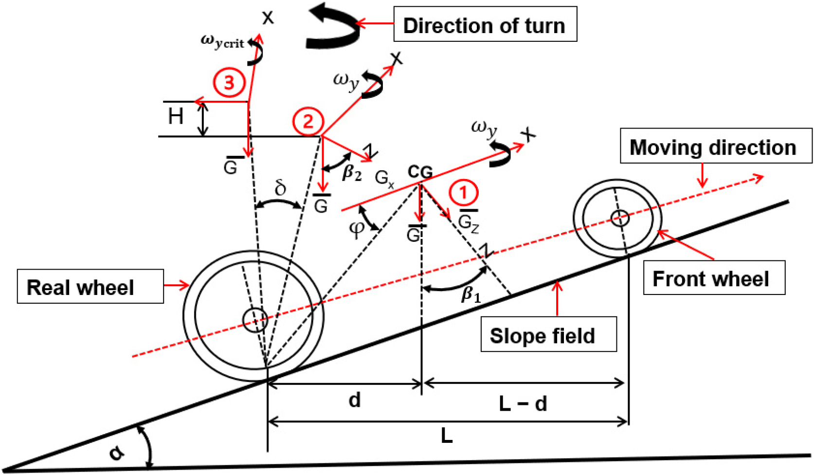
Fig. 4.
Dynamic free-body diagram of an automatic pepper transplanter on an inclined field condition. CG, center of gravity; G, gravitational force; β1 and β2, angles related to G components projected onto slope axes (x = horizontal, y = lateral, z = vertical); α, slope angle of the field; ωy and ωycrit, angular velocity and critical rollover angular velocity about the lateral y-axis; H, height of the CG above the ground; L, wheelbase or distance between front and rear wheel contact points; d, horizontal distance from rear wheel contact point to CG.
A standard right-handed coordinate system is established where the X-axis denotes the lateral direction (left-right), the Y-axis denotes the forward direction of travel, and the Z-axis denotes the vertical direction perpendicular to the ground. The transplanter operates on a slope inclined at angle α, and the CG is located at a height H above the slope surface and at horizontal distances d (from rear axle) and L-d (from front axle), with L being the total wheelbase. As shown in Fig. 4, the gravitational force G acting at the CG is decomposed into directional components: GX, GY, and GZ, depending on the slope and motion. The dynamic motion introduces angular velocities, particularly pitching angular velocity ωy, which can lead to forward or backward rollover if the CG rotates beyond the base of support.
Rear-rollover is most likely during acceleration on an uphill slope, where the rear shifting of the CG generates an overturning moment about the rear axle. This scenario typically arises when the rear drive wheels lose contact with the ground or lift during power delivery. Taking moments about the rear axle, and balancing the overturning and stabilizing moments, the condition for rear tipping becomes:
Rollover slope angle at rear side can be calculated as:
Front rollover is predominantly observed when braking downhill or during rapid deceleration, where the CG is displaced forward, causing the rear wheels to lift and the machine to pivot about the front axle. Considering the moment balance about the front axle, the tipping condition can be calculated as:
The rollover angle can be calculated as:
Simulation and validation procedures
Simulation offers valuable insights into complex systems, providing effective solutions without the need for immediate physical testing of the initial prototype. In this study, a full-scale 3D rigid body model of the developed pepper transplanter was created using a SolidWorks software (SOLIDWORKS, 2018), exported in STEP format, and subsequently imported into RecurDyn software (RecurDyn, 2024) for multibody dynamic simulation. The analysis comprised two main components: lateral rollover, assessing sideward instability from left or right tilt, and longitudinal rollover, evaluating forward or rearward instability from front or rear tilt. Both multibody dynamic simulations and inclination platform tests were performed under two conditions: unloaded (without seedling trays) and loaded (58.86 N), representing typical transplanting configurations. In the loaded condition, three trays of 19.62 N each were used, with one placed at the center and two positioned symmetrically on the left and right sides. In both scenarios, gravitational force, wheel-ground interaction, and inertial responses were considered. Additionally, the longitudinal analysis incorporated damping and frictional dynamics to better capture real-world conditions.
The geometric fidelity of the simulation model included the frame structure, wheel assemblies with passive suspension, and transplanting unit mechanisms. The center of mass was estimated through volume-weighted analysis. The key parameters obtained from the lateral rollover simulation included the rollover angle, which is the tilt angle at which the inner wheels begin to lose ground contact, rollover time defined as the time interval from the initial tilt to the occurrence of rollover, and the force required for rollover. For the longitudinal rollover simulation, the behavior of the transplanter during acceleration and deceleration was evaluated by incorporating several dynamic factors. A damping coefficient was introduced to simulate energy dissipation due to frame compliance and suspension damping, and the dynamic friction coefficient was adjusted based on the contact surface. Fig. 5 illustrates the simulated scenarios, and Table 2 presents the associated simulation parameters.
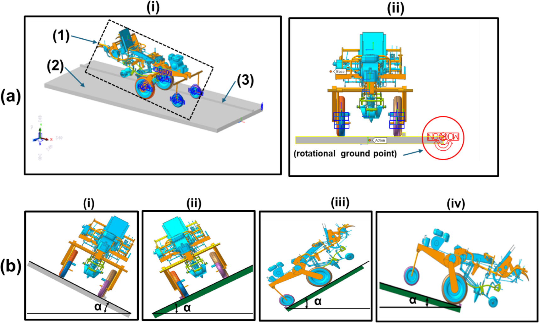
Fig. 5.
Simulations procedures: (a) Rollover simulation setup: (i) transplanter on inclination test platform: (1) inclination platform, (2) transplanter model, and (3) wheel grip rigid base, (ii) rollover simulation, (b) rollover scenarios: (i) left side, (ii) right side; (iii) front side, and (iv) rear side.
Table 2.
Rollover simulation parameters.
To validate the simulation results, a custom-built inclination test platform located at the Korea Agricultural Technology Promotion Agency in Iksan, Republic of Korea, was employed to conduct rollover tests under controlled conditions, as shown in Fig. 6. The main features of the platform included a hydraulic cylinder allowing up to 90° inclination in both lateral and longitudinal directions, and a steel checker plate surface treatment to replicate field traction. The inclination angle was measured using inclinometer and marked angle lines at 1° intervals, with safety chains installed to restrict full overturn for the protection of the transplanter and to ensure repeatability. The test setup consisted of positioning the transplanter perpendicular to the ramp incline axis. The procedure involved gradually increasing the incline angle at a uniform rate (1°/s), continuously monitoring the test with video cameras from multiple angles, and detecting wheel lift-off visually and via sensors, while manually recording the inclination angles.
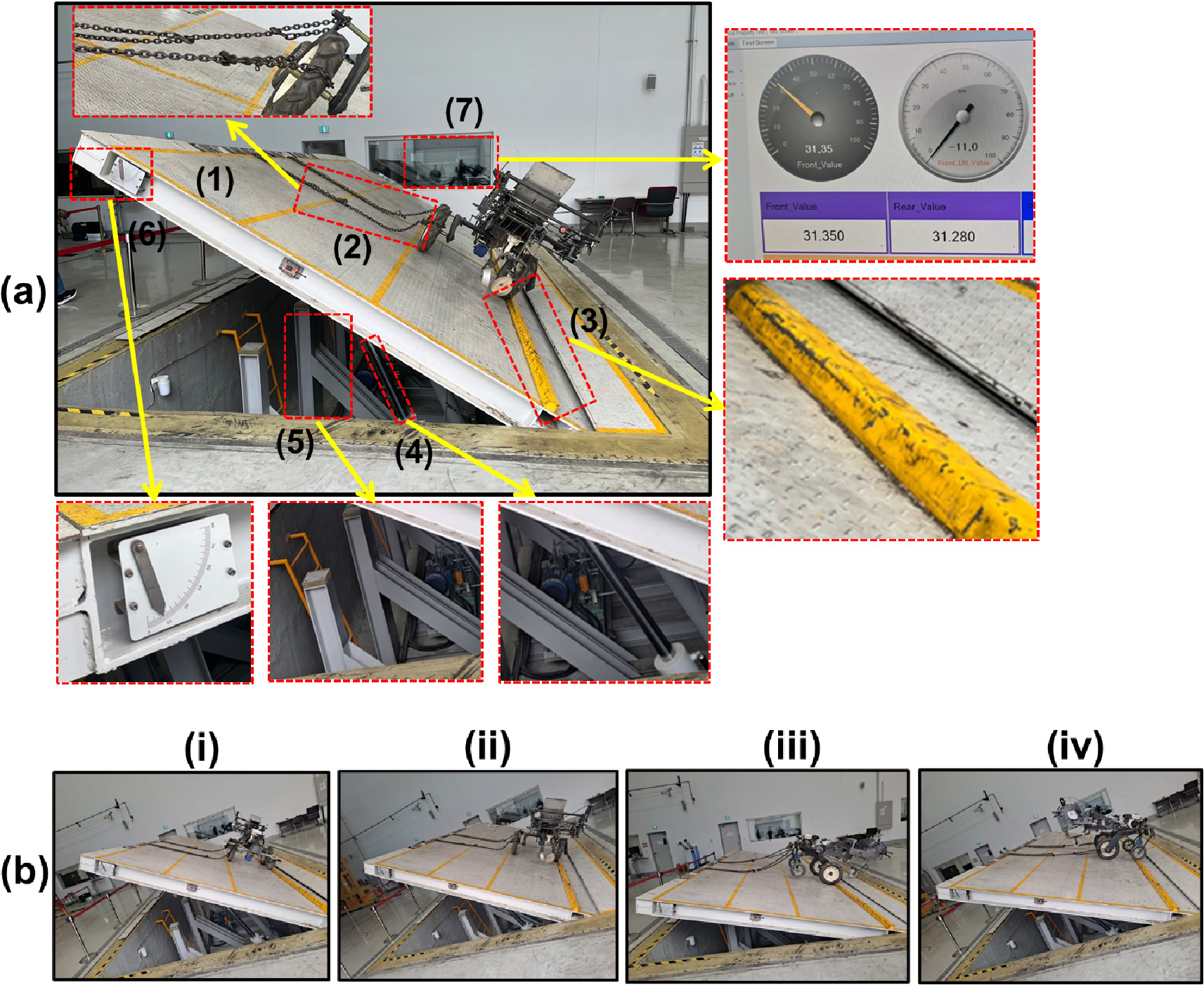
Fig. 6.
(a) Main components of the inclination test platform: (1) steel checker plate surface, (2) safety chains, (3) wheel stopper, (4) hydraulic cylinder, (5) lifting frame structure, (6) inclinometer, and (7) digital rollover angle display, and (b) rollover scenarios: (i) left side, (ii) right side, (iii) rear side, and (iv) front side.
Results and Discussion
Evaluation of center of gravity coordinates
The rollover and operational efficiency of agricultural machinery, such as transplanters, are significantly influenced by the position of the CG. An optimized CG location ensures better weight distribution, minimizes the risk of tipping, and improves field manoeuvrability. The simulation model represents a full-scale prototype of the pepper transplanter, including chassis, wheels, and planting mechanism components. The system geometry and inertial properties were accurately defined using CAD integration. Two simulation scenarios were considered: an unloaded condition, in which the transplanter operated without any seedling trays, and a loaded condition, in which the transplanter carried three 6-kg seedling trays one centrally mounted and two symmetrically placed on the left and right sides of the central axis. The additional mass applied in the simulations was 6 kg, to reflect realistic load distributions during transplanting operations. The CG coordinates were calculated with reference to the local coordinate system of the transplanter. Table 3 presents the coordinates of CG of the pepper transplanter with and without load.
Table 3.
Coordinates of center of gravity.
| Axis | Without load (mm) | With load (mm) |
| XCG | 40.43 | 22.43 |
| YCG | -116.59 | -108.29 |
| ZCG | -525.60 | -526.50 |
In longitudinal direction (X-axis), The CG moved rearward from 40.43 to 22.43 mm. This shift indicates that the placement of the seedling trays, particularly the central tray, contributed to a rebalancing of mass toward the geometric center of the machine. The resulting rearward shift enhances machine equilibrium during forward motion.
In lateral direction (Y-axis), A lateral CG movement from -116.59 mm to -108.29 mm was observed. This slight asymmetry could be attributed to mechanical non-uniformities or offset tray positioning. Though minimal, such shifts require consideration in structural design to maintain equal load distribution across the chassis and prevent bias-induced tilting on uneven terrains. In vertical direction (Z-axis), The CG lowered from -525.60 mm to -526.50 mm with the addition of the seedling trays. Lowering the CG is advantageous, as it enhances stability, reduces the chance of rollovers during turning or on sloped ground, and contributes to safe transport and field operations. The simulation results demonstrate that the designed configuration of the pepper transplanter effectively manages mass distribution under typical operational loading. The movement of the CG toward the center and downward reinforces system stability without compromising manoeuvrability.
Lateral rollover characteristics
The results from both simulation and experimental tests are presented in Table 4 and Fig. 7. In the unloaded condition, the measured rollover angle on the left side was 25.89°, slightly lower than the simulated angle of 28.20°. This discrepancy is likely due to structural flexibilities, small clearances, and non-ideal contact conditions in the test setup. On the right side, rollover angles were consistent, with the simulation yielding 27.90° and the experimental measurement showing 27.81°. Rollover times were also comparable, ranging from 3.50 to 3.82 s across both sides.
Table 4.
Rollover results in lateral conditions.
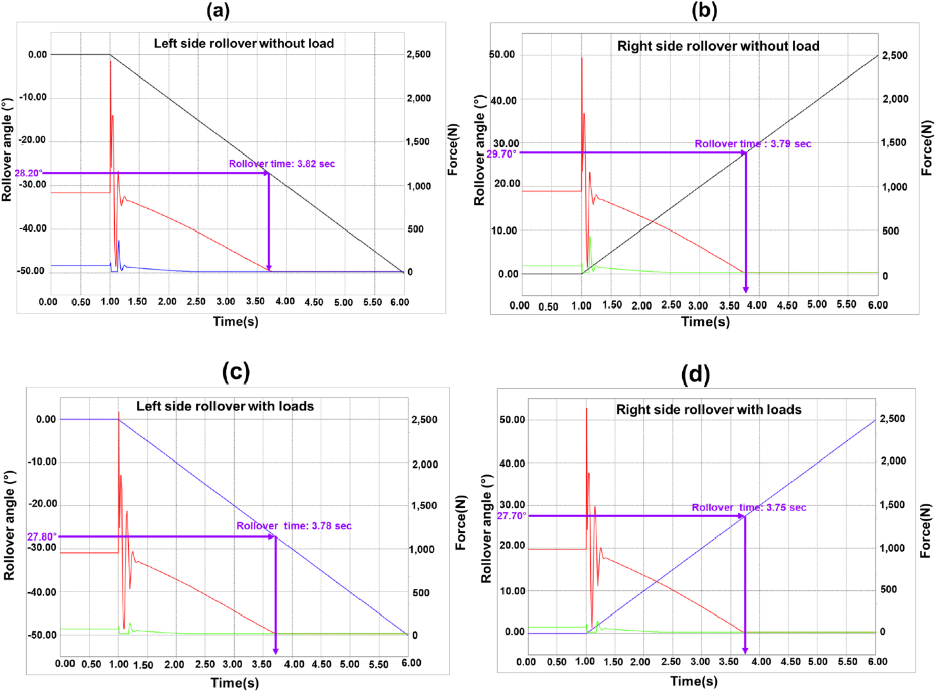
Under unloaded conditions, the measured rollover angle on the left side declined to 25.81°, compared to the simulated value of 27.80°. This reduction is attributed to the elevation of the CG and potential lateral offset induced by the added mass, resulting in increased rollover sensitivity. On the right side, rollover angles remained relatively constant, with simulated and experimental values of 27.70° and 27.79°, respectively. Rollover times exhibited minimal variation across conditions, indicating consistent behavior under symmetric load distribution. When benchmarked against the recommended lateral rollover angle for agricultural field equipment (30 - 35°) by Hwang et al. (2021), all observed values were below the lower safety threshold. This outcome suggests insufficient rollover resistance under both unloaded and loaded states, thereby reducing the operational safety margin in sloped-field applications. The findings underscore the role of mass distribution and CG in governing rollover response. Although trays were mounted symmetrically, slight deviations in installation or structural compliance may have contributed to a left-ward CG shift. This shift correlates with the lower rollover angle observed on the left side under loading, thereby increasing the probability of lateral instability. In contrast, the right side demonstrated greater rollover consistency, implying improved mass alignment and structural balance in that direction. To enhance rollover resistance, structural refinements are recommended such as widening the track width or wheelbase and lowering the CG.
Longitudinal rollover characteristics
Evaluating rollover behavior in the longitudinal direction is essential for ensuring the operational safety of transplanters on sloped or uneven terrain during both forward and backward movement. Following the approach used in the lateral rollover analysis, Table 5 and Fig. 8 present the simulated and measured rollover angles, rollover times, and applied forces in both the front and rear directions under unloaded and loaded conditions.
Table 5.
Rollover results in longitudinal conditions.
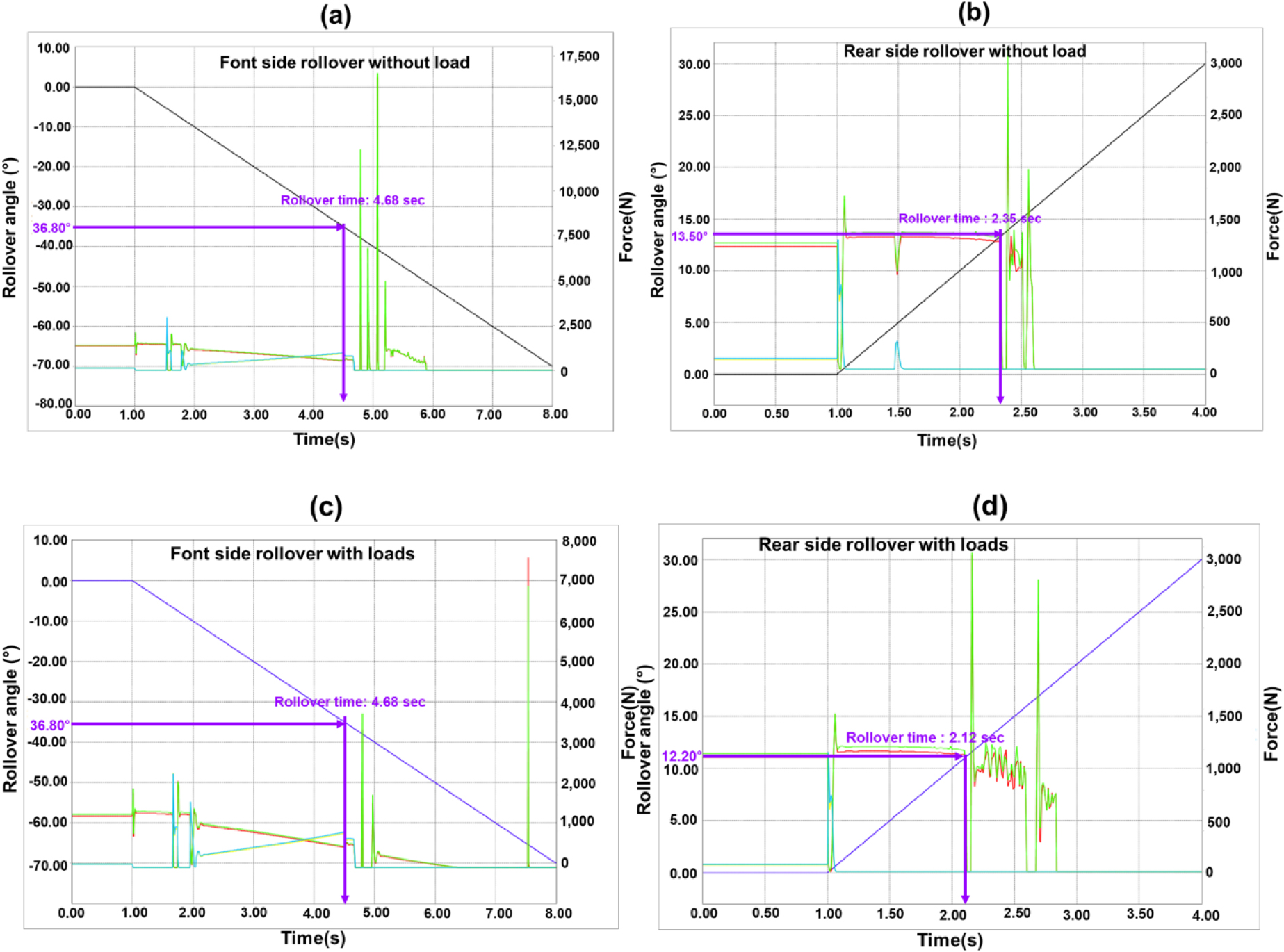
In the front direction under unloaded conditions, the measured rollover angle was 34.20°, slightly lower than the simulated value of 36.80°. This deviation may be attributed to structural compliance and mounting inaccuracies in the physical system. Despite the small variation, rollover times and force values showed consistent trends, indicating a reliable dynamic representation of the unloaded front pitch condition.
When the 58.86 N load was applied, both simulated and measured rollover angles in the front direction matched exactly at 36.80°, with rollover times recorded as 4.68 s in both datasets. This high level of agreement supports the accuracy of the simulation in capturing the onset of longitudinal instability under realistic loading. However, the forces increased from approximately 1,490 N to over 1,510 N, highlighting the additional effort required to reach the critical tipping point due to the higher moment of inertia introduced by the tray mass. The rear direction exhibited significantly lower rollover resistance. Under unloaded conditions, the simulated rollover angle was 13.50°, while the measured angle was 12.34°. When loaded, the simulated and measured rollover angles dropped further to 11.20° and 11.85°, respectively. Rollover times decreased slightly in both scenarios, with differences between measured and simulated values remaining below 0.2 s. These tight correlations confirm the suitability of the model for rear pitch rollover prediction.
Researchers have conducted both simulation and experimental studies on the rollover angles of various agricultural machines to evaluate their safe operating slopes. Kim et al. (2022) analyzed the rollover angle of a self-propelled radish harvester under different load conditions using simulation methods. Their results indicated rollover angles of approximately 27 - 28° for the front and rear right wheels, corresponding to contact forces of around 3,000 N and 2,500 N, respectively. Similarly, Chowdhury et al. (2020) applied a mathematical model and 3D simulation to investigate the overturning angle of a tractor-drawn four-row radish collector. The findings demonstrated that the machine could operate safely on land slopes of up to 30°. Furthermore, Iqbal et al. (2022) employed a 3D model of a 2.6 kW pepper transplanter to theoretically examine both static and dynamic overturning behavior. Their analysis revealed that the transplanter overturned at 29.3° in the uphill direction and 49° in the downhill direction. These reported findings are closely aligned with the results of the present study.
The results of this study further highlight that rear rollover angles are considerably lower than those of the front, indicating an inherent geometric and dynamic vulnerability at the rear section of the machine. This instability becomes more pronounced when the load mass is positioned above the rear axle, which elevates and shifts the CG rearward. Even with symmetrical tray placement, such mass distribution increases susceptibility to tipping, particularly under acceleration or during downhill operation. This emphasizes the necessity of structural and design improvements to enhance rear rollover resistance, especially under load conditions.
To address these deficiencies, several design strategies are recommended. These include repositioning the load to lower the vertical CG, incorporating rear counterweights to rebalance mass distribution, and using wider rear wheel tracks to extend the rollover threshold. Structural enhancements such as reinforced front chassis members and anti-pitch bars are also advised to suppress sudden longitudinal instability.
Conclusion
This study evaluated the rollover characteristics of a 3.4 kW walking-type automatic pepper transplanter through multibody dynamic simulation and experimental validation using an inclination platform. Rollover performance was examined in both lateral and longitudinal directions under unloaded and loaded conditions, with emphasis on mass distribution and the CG.
Under lateral conditions, simulated rollover angles ranged from 27.70 to 28.20°, while measured values ranged from 25.81 to 27.81°, showing close agreement. A minor leftward CG shifts under load reduced the left-side rollover angle. All values were below the safety range of 30 - 35°, confirming insufficient lateral rollover resistance. Rollover times remained relatively stable at 2.2 - 2.3 s, reflecting balanced dynamic behavior under symmetrical loading.
In longitudinal conditions, the front direction displayed strong rollover resistance, with both simulation and experimental values converging at 36.80° under load. Rollover forces increased slightly with load due to higher inertia. By contrast, the rear direction showed the greatest instability, with rollover angles decreasing from 13.50 to 11.20° in simulation and from 12.34 to 11.85° in experiments. The shortest rollover times, between 2.12 and 2.24 s, were also recorded at the rear, confirming greater tipping susceptibility caused by rearward CG displacement.
The findings demonstrate that while lateral and front rollover resistance are structurally acceptable, the rear direction presents a critical risk. To mitigate this, the CG should be repositioned lower and closer to the center of the transplanter. Recommended improvements include adding rear counterweights, widening the rear wheel track, installing anti-roll bars, and reinforcing the front-end structure. The outcome of this study provides a preliminary safe operating slope, while further validation is required under real farming conditions.
