

Introduction
Materials and Methods
Working principle and modelling of the wheel-driven hopper planting mechanism
Simulation of the planting mechanism model
Results and Discussion
Wheel diameter and planting hopper trajectory
Velocity and acceleration
Seedling deposition
Conclusion
Introduction
Vegetables are an essential part of a healthy diet, providing vital nutrients, including vitamins A, C, and K, as well as potassium, calcium, magnesium, and fiber, which enhance immunity, aid digestion, regulate blood sugar, and reduce the risk of cardiovascular disease, obesity, diabetes, cancer, and other chronic illnesses (Ramya and Patel, 2019). Global vegetable production in 2023 reached 2.1 billion tons, reflecting a 1% increase from 2022, while demand for fresh vegetables is projected to grow by 2.8% from 2022 to 2028, with China leading production at 594 million tons, followed by India at 145 million tons and the U.S. at 33 million tons (FAO, 2023). Labor shortages and reliance on manual agricultural operations have led to significant declines in vegetable production and cultivation areas in several counties, resulting in failure to meet market demand (Rutledge and Mérel, 2023). South Korea experienced a notable decrease in production area from 247,000 to 217,000 ha between 2014 and 2023 (KOSTAT, 2023). In 2022, the mechanization rate for vegetable farming in South Korea was 63.3%, while seedling transplanting had a significantly lower rate of 12.6% compared to other operations, with approximate values of 99.8% for cultivation, 94.8% for pest control, 76.9% for plastic mulching, and 32.4% for harvesting (RDA, 2023). For sustainable vegetable production, the adoption of agricultural machinery, particularly for seedling transplanting, is essential to enhance mechanization rates, reduce labor dependency, and improve yields (Nourani and Bencheikh, 2020).
Based on the level of automation, mechanical transplanters are classified into semi-automatic or manual-assisted and fully automatic transplanters. Semi-automatic transplanters require an operator to manually feed seedlings, while fully automatic transplanters are equipped with an automated system for seedling picking, transferring, and planting (Shi et al., 2023). Based on the type of hopper-holding component, the planting mechanism can be classified into link-driven, wheel-driven, and rotary gear-driven types, which utilize the rotational motion of links, wheels, or gears to drive the planting hopper and place seedlings into the soil (Habineza et al., 2024).
Kinematic analysis uses mathematical and simulation models to evaluate the motion characteristics of a prototype in a virtual environment, enabling the prediction of operational characteristics in real-field conditions (Rafeeq et al., 2022). Researchers used theoretical kinematic models to determine the operating characteristics of the vegetable transplanting mechanisms of the prototype for predicting field performance and efficiency. Shi et al. (2024) designed and conducted field experiment of a duckbill-type planting mechanism for an automatic transplanter targeting densely planted vegetables. The developed kinematic theoretical model determined the parameter of opening and closing duckbill and field test determined the planting rate of 96.62% and planting spacing variation coefficient of 3.55%. Choi et al. (2024) conducted a theoretical kinematic analysis of a sliding-type picking mechanism for automatic pepper seedling transplanters. The developed kinematic simulation and vector-loop model determined the best combination of link lengths, with optimal velocity (0.274 and 0.199 m·s-1) and acceleration (2.494 and 8.249 m·s-2) along the -X and -Y axes, respectively, at a driving link speed of 30 rpm. The study identified optimal link length combinations that resulted in effective seedling picking performance. Zuli et al. (2011) conducted a kinematic analysis and performance experiment on a cantilever cup vegetable transplanter. Based on the developed theoretical model, a prototype was manufactured, and validation test results showed a seedling upright rate of 97.79%, a planting depth coefficient of 0.87%, and a seedling damage rate of 2.19%.
To address the challenges posed by labor shortages and the drudgery involved in vegetable farming, this study conducted a theoretical kinematic analysis using both mathematical models and simulations to determine the optimal kinematic parameters for a wheel-driven hopper-type planting mechanism used in vegetable transplanters. The analysis focused on identifying the optimal values of wheel diameter, velocity, acceleration, hopper trajectory, and forward speed required for efficient operation, ultimately enhancing transplanting precision and minimizing seedling damage. The study ensured precise control of the rotational speed of the wheel to facilitate the smooth movement and release of vegetable seedlings into the planting furrow.
The objective of this study was to conduct a theoretical kinematic analysis incorporating both mathematical modelling and simulations of a wheel-driven hopper-type planting mechanism, to calculate the velocity, acceleration, working trajectory, and forward speed required for the efficient transplanting of vegetable seedlings.
Materials and Methods
Working principle and modelling of the wheel-driven hopper planting mechanism
Three-dimensional (3D) model of the wheel-driven hopper planting device was designed to evaluate vegetable seedling planting mechanism. As shown in Fig. 1, the wheel-type planting mechanism includes a wheel, wheel support, roller, roller guide, and the planting hopper. The common operation of vegetable transplanters integrates the seedling supply, picking, and planting mechanisms corresponding on the seedlings transfer from the nursery tray, conveying them to the planting hopper, placing them into the planting furrow, and firming the soil around them on both sides (Habineza et al., 2023).
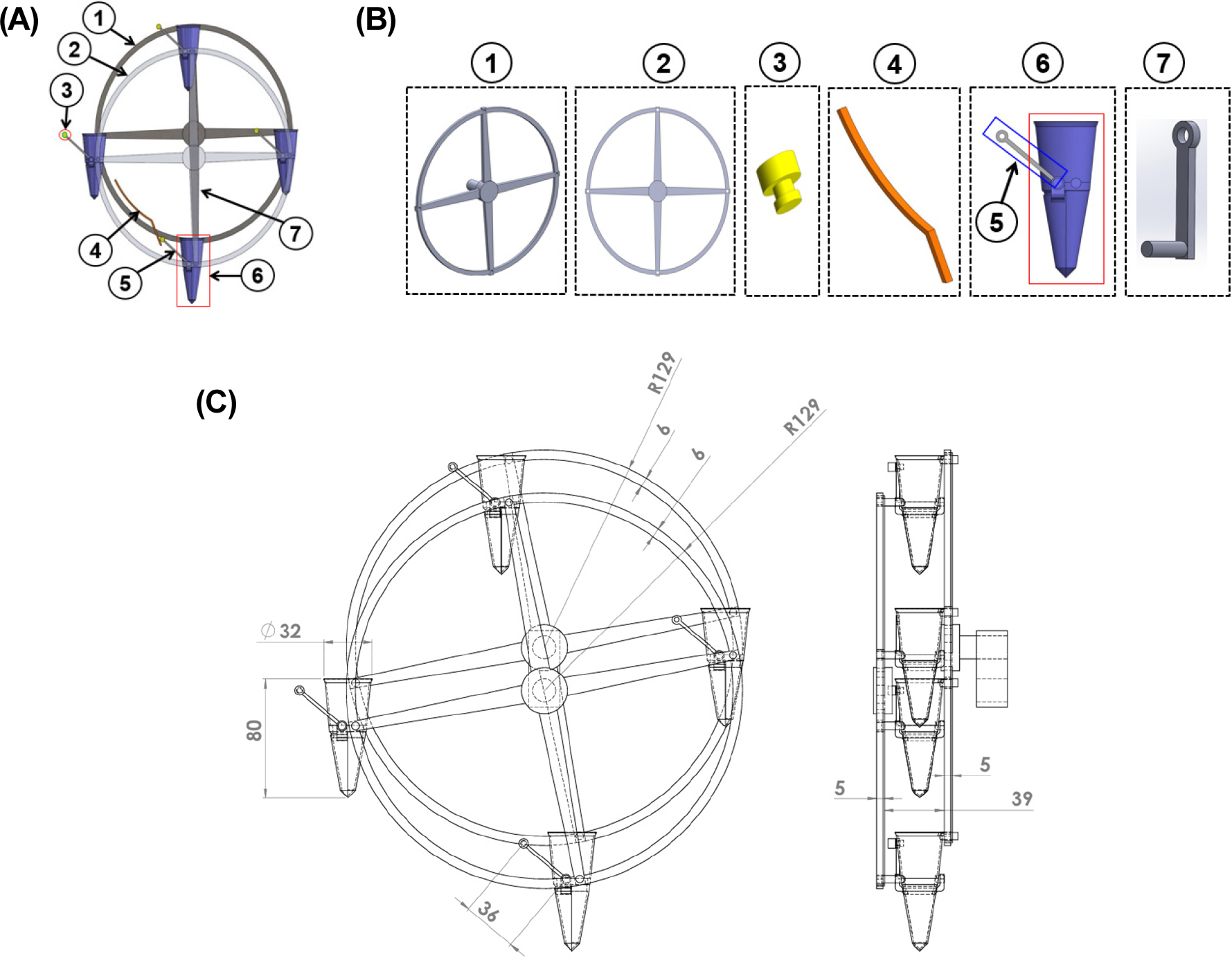
Fig. 1.
(A) 3D model of the wheel-driven hopper-type planting mechanism: (1) driving wheel, (2) wheel support, (3) roller, (4) roller guide, (5) hopper opener, (6) planting hopper, and (7) connecting rod; (B) Overview of the main components of the planting mechanism, and (C) 3D drawing of the wheel-driven hopper-type planting mechanism, showing the dimensions of all components.
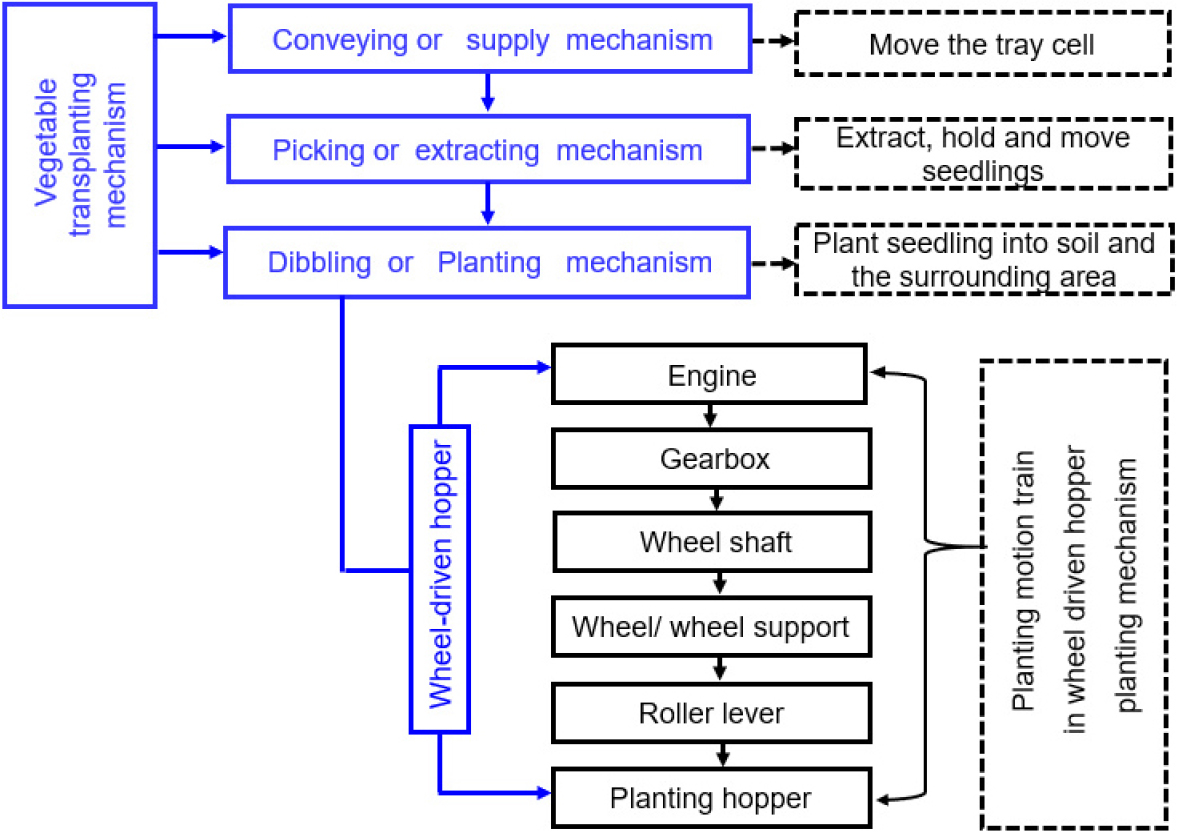
In a wheel-driven hopper-type planting mechanism, the motion of the planting components begins with engine start-up and activation of the planting transmission lever. This action transmits rotational force through a shaft, driving the wheel and the attached hopper assembly, which causes the entire frame to rotate. The wheel revolves around a fixed axis, guiding each hopper along a circular trajectory. When a hopper reaches the lowest point, the roller guide contacts the roller mounted on the hopper, triggering the bottom flap to open and releasing the seedling vertically into the planting furrow. After the seedling is placed in the furrow, a molding wheel presses the surrounding soil to firm it around the seedling. The hopper then moves upward, the flap closes, and the mechanism prepares to receive the next seedling (Sharma and Khar, 2024). Fig. 1 shows the detailed structural layout of the mechanism, while Fig. 2 shows the working principle flowchart of the wheel-driven hopper-type planting mechanism.
The kinematic modelling of the planting device considers the operational components to optimize performance. Key considerations include preventing seedling damage, forming an appropriate planting hole, placing the seedling vertically into the furrow, firming the root zone, and ensuring uniform planting for successful crop establishment (Reis and Forcellini, 2002). The modelling of the designed planting mechanism considers the mechanical structure of its main operational components, including a drive wheel, a wheel support frame, and four planting hoppers symmetrically mounted on a circular frame, as shown in Fig. 3. Under static conditions, the rotational motion of the driving wheel allows the duckbill to follow a circular trajectory that defines both the upper point for receiving the seedling from the supply mechanism and the lower point for depositing it onto the soil surface. Under dynamic conditions, the transplanter moves forward at a suitable constant speed, generating a scalloped trajectory in coordination with the opening and closing actions of the duckbill. Fig. 3 illustrates the motion path and key action points of the hopper during seedling planting.
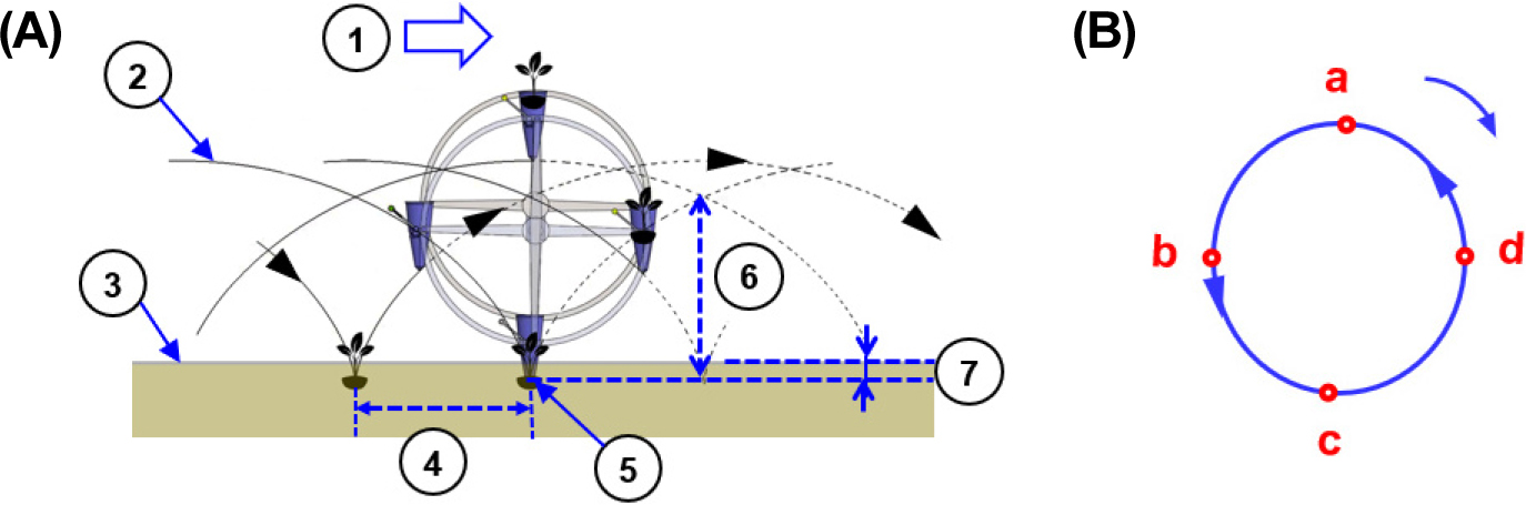
Fig. 3.
Planting trajectory of the wheel-driven hopper-type planting mechanism: (A) Motion of the planting hopper under dynamic conditions: (1) Forward direction, (2) Planting track, (3) Ground surface, (4) Planting spacing, (5) Planting point, (6) Track height, and (7) Planting depth; and (B) Motion of the hopper under static conditions: (a) Seedling supply point, (b) Duckbill opening point, (c) Seedling planting point, and (d) Duckbill closing point.
Fig. 4 presents the kinematic motion of the planting hopper in the wheel-driven, hopper-type mechanism. A three-dimensional representation of the mechanism is shown in Fig. 4A. To derive the key kinematic parameters namely hopper position, velocity, and acceleration requirements a vector loop model of the mechanism was established. These parameters were calculated using mathematical equations and subsequently validated through simulation analysis. As illustrated in the planar vector loop diagram in Fig. 4B, the outer circle represents the trajectory followed by the rotating frame, which is driven by the main wheel revolving around a fixed center point (O). This circular path also denotes the initial positions of the four planting hoppers, labelled A, B, C, and D. The inner circle shows the secondary rotation of the hoppers about their own axes (around O′). The vector loop model (O → A → A′ → O′) included vector (O′O) representing the vector from the ground center to the wheel center, (OA) is the vector from the wheel center to the hopper, and (AA′) is the vector from the top of the hopper to the seedling release point in static motion). The arrows for (V and V′) show the directions of velocities of hoppers at points C and C′, respectively.
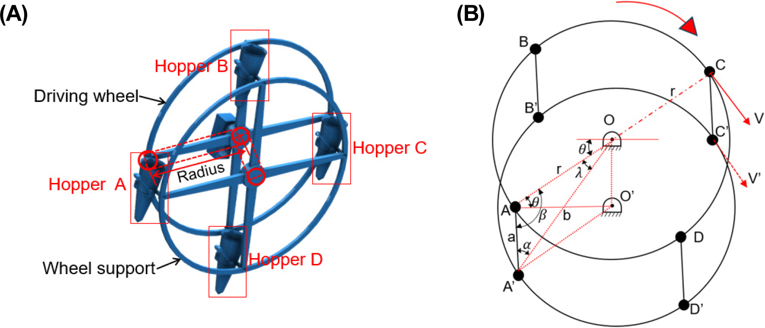
The position, angular velocity, and angular acceleration of the planting hopper can be calculated using Eqs. (1), (2), (3), respectively.
where, A, B, C and D are points of the hoppers connected to the driving wheel; A′, B′, C′ and D′ are points of the hoppers connected to the wheel support; O and O′ are center points of the driving wheel and hopper frame; V and V′ are the tangential velocities indicating rotational motion; r is the radius of the wheels from fixed point O to each hopper; a is the length of the hopper connection from the driving wheel to the wheel support frame wheel; b is the distance from O to A′; 𝜃 is the angle always measured from the X-axis and it is should always be less than 90° (0 ≼ 𝜃 ≼ 90); 𝛼, 𝜆, and 𝛽 are the angular parameters representing the rotation of the wheel and hoppers that makeup triangle OAA′; 𝜔 is the angular velocity; σ is the angular acceleration; T is the period of rotation for a complete one full revolution, and t is time.
Simulation of the planting mechanism model
Kinematic simulations of the wheel-driven hopper-type planting mechanism were conducted to validate theoretical models and optimize key design variables such as wheel diameter and rotational speed. A 3D model was developed using commercial simulation software SOLIDWORKS (Dassault Systèmes, 2018) to evaluate the kinematic performance of the planting device under both static and dynamic conditions.
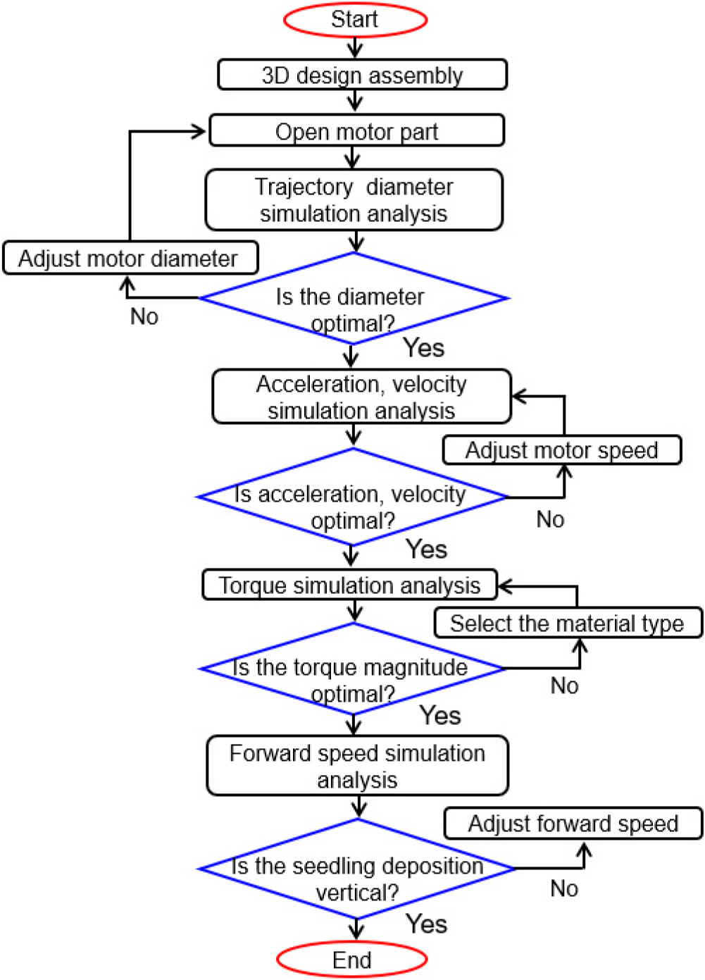
The simulation process began with 3D model assembly and proceeded through stages including trajectory diameter, acceleration and velocity, torque, and forward speed. At each stage, parameters were evaluated and adjusted as necessary, concluding when vertical seedling deposition was achieved. The wheel had a thickness of 6 mm, a 36 mm-long hopper opener, a 32 mm hopper mouth diameter, and an 80 mm hopper height. Six trials with driving wheel diameters of 150, 200, 250, 300, 350, and 400 mm were conducted to evaluate planting trajectories. Additionally, eight trials with rotational speeds of 5, 10, 15, 20, 25, 30, 35, and 40 rpm were performed to assess the velocity and acceleration needed for smooth vegetable seedling transplanting. The simulation validated the theoretical analysis, confirmed the required planting trajectory, and ensured precise vertical placement of the seedlings. Steel alloy 1,020 was selected for the body cover and other components due to its strength and durability, making it suitable for agricultural applications. Its physical properties include a density of 7.85 × 10³ kg·m-3, a modulus of elasticity of 207 GPa, a Poisson’s ratio of 0.3, and a yield strength of 210 MPa. Fig. 5 illustrates the simulation flowchart, and Table 1 presents the simulation parameters.
Results and Discussion
Wheel diameter and planting hopper trajectory
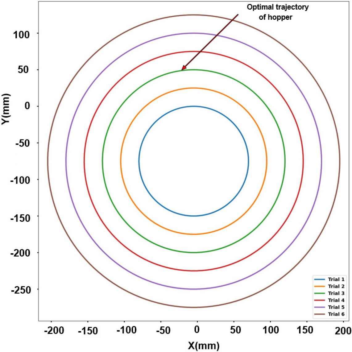
Considering the planting component as a crucial part of the vegetable transplanter, six simulation trials were conducted to analyze the effect of wheel diameter on the planting path trajectory of the planting hoppers. Wheel diameters ranged from 150 to 400 mm, while the customized dimensions of the hopper opener length, hopper mouth diameter, and hopper height were kept constant at 36 mm, 32 mm, and 80 mm, respectively values closely matching those used in other leafy vegetable transplanter (Shi et al., 2024). Once power was applied to the wheel shaft, the planting device rotated in a circular motion, while the forward operating speed caused the planting hopper to advance in a scalloped pattern, releasing seedlings into the soil. The static motion of the wheel-driven hopper generated a planting hopper trajectory composed of a series of concentric circular paths, resulting from the uniform and consistent placement of the hoppers, which released vegetable seedlings at the lowest point of their path. The wheel diameter directly influenced both the height and width of the planting hopper trajectory, which together formed a complete circular path. The total displacement along the X-axis (vertical direction) was equal to that along the Y-axis (horizontal direction). The optimal wheel diameter was approximately 250 mm, resulting in an optimal planting hopper trajectory of about 249.9 mm on both axes closely matching the wheel diameter. This corresponds to the target optimal trajectory for precise and vertical seedling placement. Table 2 and Fig. 6 illustrate the wheel diameters used in the simulation trials and the corresponding planting hopper trajectories.
Table 2.
Simulation trials with varying wheel diameters and their corresponding planting hopper trajectories.
Velocity and acceleration
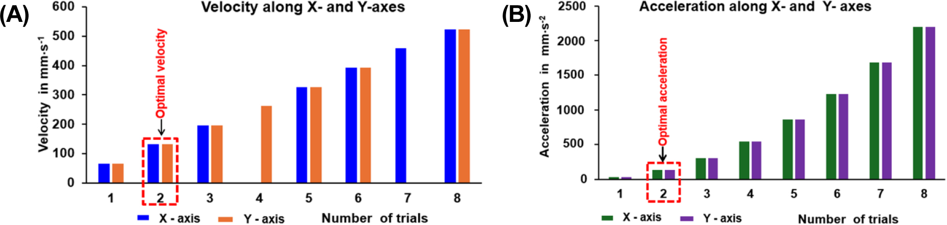
Kinematic simulation analysis of the seedling planting device was performed using the simulated motion of the planting hopper, with coordinate data along the -X and -Y axes used to calculate velocity and acceleration, to assess whether the hopper motion ensures timely and accurate seedling deposition. The optimal wheel diameter and predefined planting trajectory were used to evaluate the peak velocity and acceleration of the hopper during the transfer of vegetable seedlings from the supply unit to the planting furrow under varying motor speeds. Among the eight trials, a motor speed of 10 rpm demonstrated an optimal balance between operational efficiency and planting precision, yielding peak velocity and acceleration values of 131 mm·s-1 and 137 mm·s-2, respectively, along both the X- and Y-axes, with a corresponding planting rate of 39 seedlings per minute. When operating below or above these peak values, the hopper failed to receive and release seedlings at the correct timing, potentially causing seedling damage or delays in the planting process. At speeds beyond 10 rpm, velocity values increased progressively, which may compromise seedling placement accuracy due to higher inertial forces and increased hopper vibrations. Table 3 shows simulated velocity and acceleration values at different motor speeds, and Fig. 7 illustrates their graphical representation.
Table 3.
Velocities and accelerations of the planting hopper at different motor speeds.
Seedling deposition
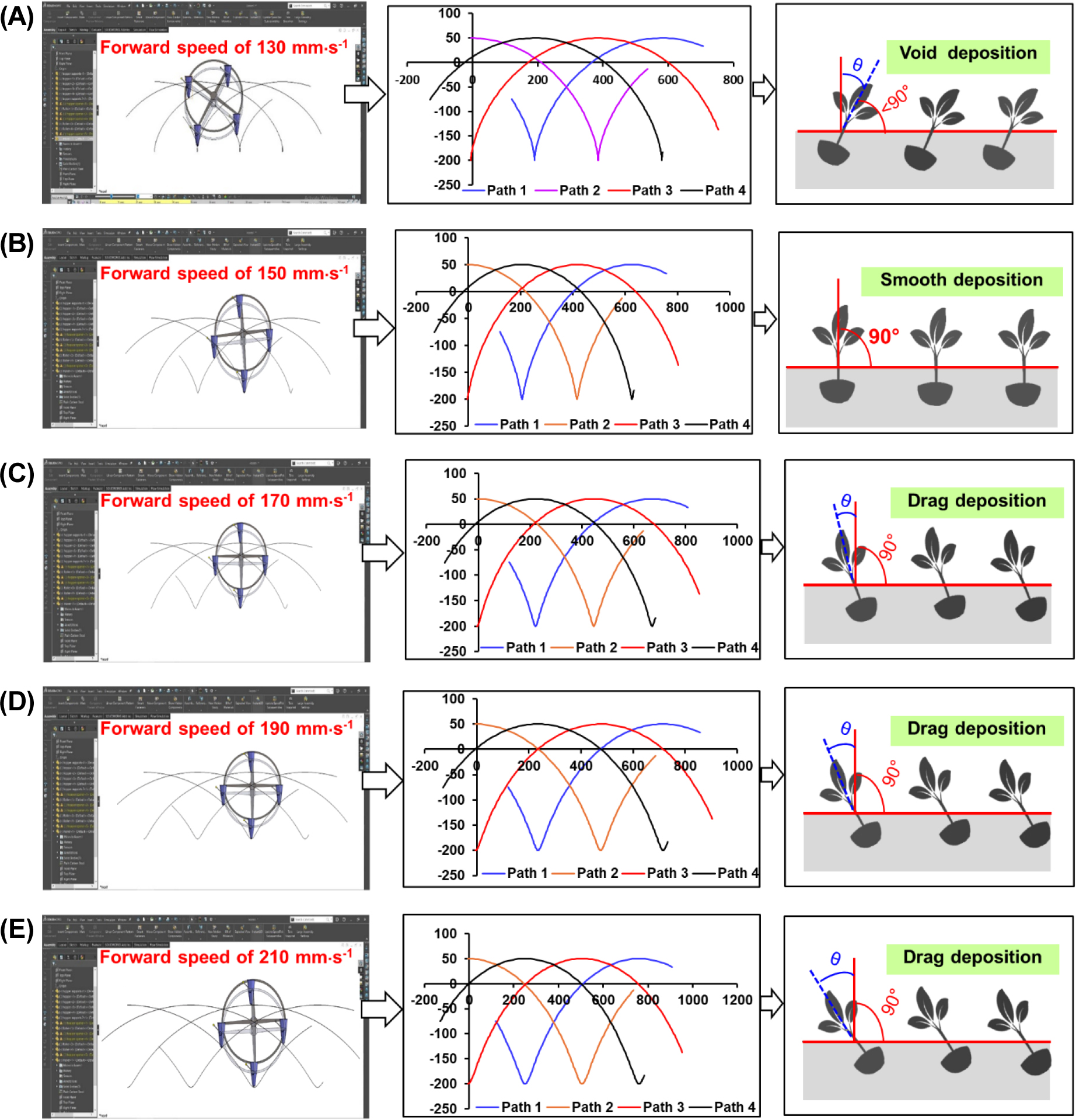
The analysis of seedling deposition was carried out by incorporating both the rotational motion of the planting arm and the translational movement of the transplanter, as these dynamics jointly influence the precision of seedling placement. Forward speeds ranging from 130 to 210 mm·s-1 were tested at a constant rotational speed of 10 rpm. These variations affected the planting trajectory, the interaction angle between the seedling and the soil, the within-row planting spacing, and seedling anchorage. At a low speed of 130 m·s-1, the planting hoppers produced a highly clustered planting trajectory with a shallow displacement arc, placing seedlings at a spacing of 130 mm within the row. The seedlings tended to fall prematurely and failed to anchor vertically, resulting in a seedling-soil contact angle of less than 90° (θ < 90°), which led to missed plantings or improper deposition. At a forward speed of 150 mm·s-1, the planting hoppers formed a balanced trajectory with a consistent arc and a planting spacing of 150 mm within the row, resulting in a perpendicular orientation of the seedling to the soil surface with a contact angle of 90°. The seedlings were planted in an upright position with good soil contact, minimal transplant shock, uniform spacing, and maximum establishment success, representing an ideal condition in which seedling deposition and forward speed were well synchronized. At forward speeds greater than 150 mm·s-1, the planting hoppers exhibited a planting trajectory characterized by elongated arcs and increased displacement. Seedlings tilt backward with (θ > 90°), compromising stability and causing uneven soil coverage on both sides of the planted seedling, which leads to weaker anchorage and delayed root establishment. Table 4 presents simulated planting spacing and seedling deposition characteristics at different speeds, while Fig. 8 illustrates the representation of deposition characteristics at various forward speeds.
This study identified the optimal diameter of the wheel-driven planting hoppers as 250 mm. The hoppers rotated to plant vegetable seedlings along a circular trajectory measuring approximately 249.9 mm in both the vertical and horizontal directions, closely aligning with the wheel diameter. An appropriate forward speed of 150 mm·s-1 was established for smooth and upright seedling placement, resulting in a soil contact angle near 90° and a within-row spacing of 150 mm. Simulation results showed a peak velocity of 131 mm·s-1 and a peak acceleration of 137 mm·s-2 for the planting hopper along both the X- and Y-axes at a motor speed of 10 rpm, achieving a planting rate of 39 seedlings per minute. Various studies have employed kinematic simulations and field experiments to analyze various vegetable seedling transplanting mechanisms, focusing on key parameters such as velocity, acceleration, planting trajectory, forward speed, and planting angle. Iqbal et al. (2021) investigated the hopper-type, gear-driven dibbling mechanism of a two-row automatic pepper transplanter. The analysis findings revealed the horizontal displacement of the hopper ranging from ±40 mm to ±90 mm, while the vertical movement varied from 7 to 157 mm in the upward and from -313 mm to -463 mm in the downward. The mechanism exhibited maximum velocities between 1,003 and 1,945 mm·s-1 and peak accelerations between 6,316 and 12,238 mm·s-2. These values were recorded while the transplanter operated at 60 rpm, planting two seedlings per second at a forward speed of 300 mm·s-1. Du et al. (2018) conducted a kinematic simulation of the hopper motion in an up-film transplanter to minimize damage to the mulch film during planting. The optimal planting trajectory of the hopper was determined to be 200 mm at a forward speed of 251 mm·s-1. Under these conditions, the minimum observed damage was 23.0 mm on the surface of the mulch film and 53.9 mm at the beneath. Ali et al. (2024) performed a kinematic analysis of a cam-follower-type transplanting mechanism used in a biodegradable potted cabbage transplanter. The optimal component lengths were determined as 153 mm for the dibbling hopper, 50 mm for the driving link, 120 mm for both the connecting arm and the guide bar, and 220 mm for the end-effector link. The mechanism achieved velocities of 284 and 1,379 mm·s-1, and accelerations of 1,241 and 8,664 mm·s-2 along the X and Y axes, respectively. Although there were differences in the kinematic parameter results across studies, the underlying simulation principles from previous research were respected. The discrepancies were influenced by factors such as the type of mechanism, the dimensions of the main operational components, and the crop type.
Table 4.
Simulated seedling spacing and deposition characteristics at various forward speeds.
Conclusion
In this study, the seedling planting mechanism of a vegetable transplanter was theoretically analyzed to determine the optimal diameter of the wheel-driven hoppers and to evaluate the kinematic parameters required for the smooth and vertical placement of vegetable seedlings. The optimal combination of dimensional components for the wheel-driven hopper planting mechanism, the planting trajectory and the kinematic parameters of the planting unit was determined. The working trajectory of the planting hopper was mathematically derived using a vector loop method and validated through a kinematic simulation model. The optimal component dimensions of the planting unit in the mechanism were determined to be a wheel diameter of 250 mm, a wheel thickness of 6 mm, a hopper opener length of 36 mm, and a hopper height of 80 mm, with the generated optimal trajectory along a circular path measuring 249.9 mm in both the vertical and horizontal directions. An appropriate forward speed of 150 mm·s-1 was identified to enable smooth planting of vegetable seedlings in an upright position, resulting in a soil contact angle close to 90°, with a peak velocity of 131 mm·s-1 and a peak acceleration of 137 mm·s-2 for the planting hopper along both the X- and Y-axes. The theoretical analysis confirmed the influence of forward speed on the seedling deposition position, soil contact angle, and plant establishment, which may be validated through actual tests under real field conditions.
