

Introduction
Materials and Methods
Overall structure and working principle of the picking mechanism
Concept modelling of the automatic seedling picking mechanism
Kinematic modelling using vector loop method
Simulation and validation procedures
Results and Discussion
Position of the gripper during the seedling transplanting process
Velocity and acceleration of the gripper
Evaluation of seedling picking performance
Conclusion
Introduction
Pepper (Capsicum annuum L.) is one of the most important seasonal vegetable crops, cultivated during specific periods aligned with suitable climatic conditions (Koundinya et al., 2018). Labor shortages in agricultural operations hamper task completion, leading to diminished productivity and an inability to meet market demand (Vaishnavi and Manisankar, 2022). The use of a mechanical transplanter for pepper seedlings significantly enhances the efficiency of the transplantation process, which includes extracting seedlings from nursery trays, transferring them via a conveying device, and planting them in the soil within a short time (Habineza et al., 2023). The picking mechanism is an essential part of the seedling transplanting process that moves the maximum amount of root mass of the seedling without harming the roots, stems, or leaves and ensures the proper planting trajectory, which directly impacts crop growth (Zhao et al., 2020; Periasamy et al., 2022).
A successful seedling extraction process considers the agronomic characteristics of the seedling and the mechanical design of the picking component (Han et al., 2023). The picking angle toward the seedling tray and the moisture content of the seedling medium enables the smooth picking mechanism (Zhang et al., 2022). The necessary picking angle with respect to the tray cell must be smaller than the taper of the tray cell, and the moisture content level of the seedling medium must be controlled as low-moisture lumps are easily crushed, while wet root lumps are soft and may make it difficult for the picking component to grasp the seedlings and hold onto the surrounding soil (Liu et al., 2019). Several researchers have conducted experiments on the performance of seedling picking devices in relation to root lump moisture content, aiming to identify the optimal range that minimizes seedling damage and defects during the transplanting process. Ryu et al. (2001) evaluated the performance of a sliding-type seedling picking device and determined that the optimal root lump moisture content ranged from 55 to 65%, resulting in a success rate exceeding 90%. Mao et al. (2014) developed a pincette-type pick-up device for automatic transplanting seedlings; the optimal root lump moisture content ranged from 55 to 60% with a success ratio of 90.71%. Also, Liu et al. (2024) designed and evaluated a seedling pick-up device for tomato transplanting. The device was analyzed through simulations using the ADAMS algorithm, and its performance was validated on a laboratory test bench. The results showed a seedling damage rate of 7.2% and a success rate of 90.3%.
To address the challenges of labor shortages, seedling damage, and transplanting success during the transplanting process, this study conducted a kinematic analysis of a pepper transplanter under development, using mathematical modelling, simulation, and field validation to determine the kinematic parameters of a gripper-type automatic picking mechanism, thereby ensuring smooth seedling transplanting while minimizing mechanical stress. The analysis focused on determination of the appropriate length and base height of the gripper, and corresponding position, velocity and acceleration followed by field test for assessment of the seedling transplanting success. The objective of this study was to conduct a kinematic analysis to optimize the motion dynamics of a gripper-type picking mechanism by integrating a mathematical model, simulations, and field tests, thereby supporting the development of a reliable, efficient, and minimally invasive seedling transplanting for mechanized pepper cultivation.
Materials and Methods
Overall structure and working principle of the picking mechanism
A 3D model of the picking device was developed to evaluate the performance of the automatic seedling-picking mechanism for a pepper transplanter under development. The transplanter underdeveloped included a synchronized gripper-type picking mechanism, a rotary tray conveying mechanism, and a link-driven hopper planting mechanism. The entire picking mechanism consisted of a fixed slot, connecting link, rotary gear box, slider, and gripper holding dual pins as shown in Fig. 1.
The gripper with dual pins operated through a clamping motion to transfer the seedlings from the cell tray and release them into the planting hopper. The planting hopper received the seedlings from the tray cells of the conveying mechanism, planted them in the soil, and covered the surrounding area around each seedling. The entire transplanting mechanism functioned in a repetitive, rotary manner, synchronized with the engine operation and transplanting throttle lever settings.
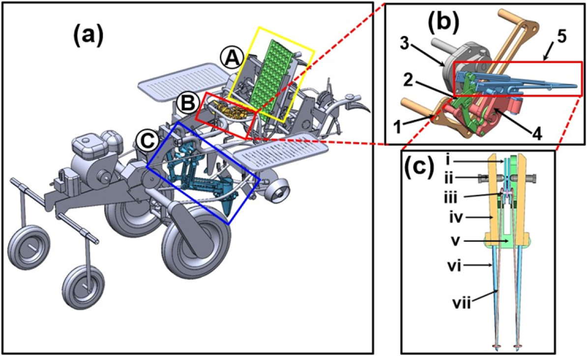
Fig. 1.
(a) 3D model of the seedling-picking mechanism showing the main parts: (A) tray conveyor, (B) picking component, and (C) planting component; (b) main parts of the clamp-type picking component: (1) fixed slot, (2) connecting link, (3) gearbox, (4) slider, and (5) gripper; and (c) main parts of the gripper: (i) pin contact slide, (ii) pin contact pivot, (iii) pin joint, (iv) gripper support, (v) guide plate/pull rod, (vi) pickup pin/needle, and (vii) pin support.
Concept modelling of the automatic seedling picking mechanism
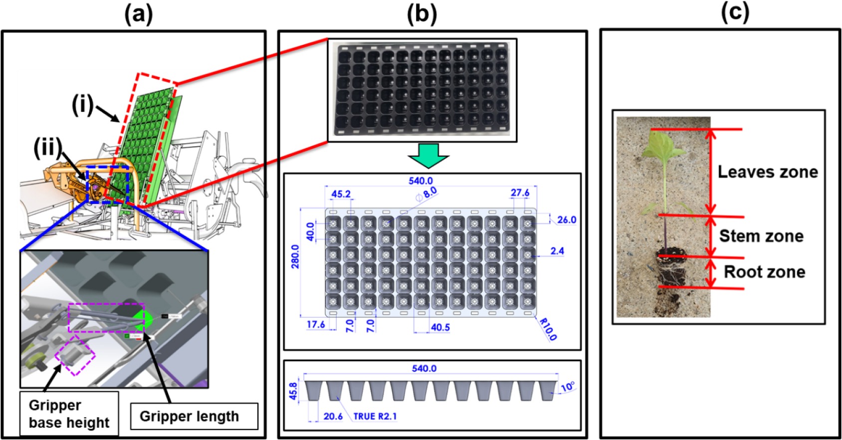
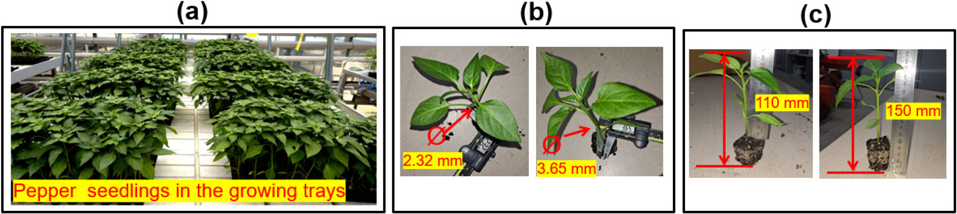
The picking mechanism was modeled based on the physical characteristics of pepper seedlings and the design features of the picking device to ensure successful transplanting while avoiding mechanical stress to the seedlings as shown in Fig. 2. Pepper seedlings intended for transplanting using mechanical equipment, such as transplanters, should be grown for 45 days under controlled moisture conditions in the seedling medium to develop the appropriate height, stem diameter, and leaf area required for smooth and efficient picking (Iqbal et al., 2022). The seedling-picking device should be flexible enough to maneuver toward the tray cell to minimize seedling stress and prevent picking failure (Han et al., 2023). The designed picking unit features a gripper fastened with a pair of pins, which extract the seedling from the growing medium and gently grasp, hold, lift, and release it into the hopper of the planting device through a clamping motion.
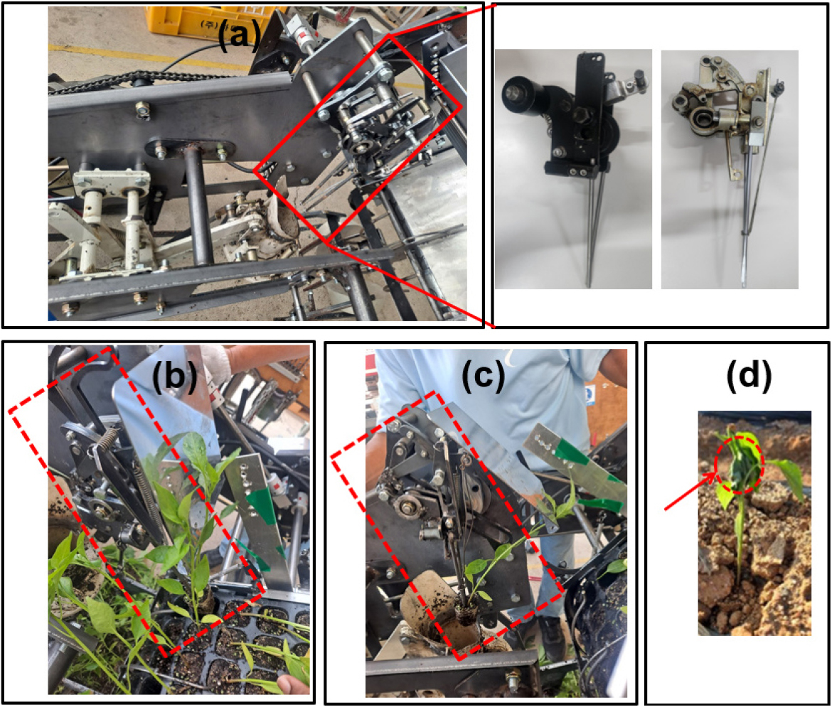
The transplanting process incorporates the engine start and the engagement of the transplanting throttle lever, which transmits power to the gripper via the drive gearbox shaft and sprocket chain. This mechanism enables the pickup pins to move toward the seedling, allowing them to penetrate the tray cell wall through the root lump. The tension applied by the guide plate caused the pair of pins to retract and compress, allowing the pull rod arm to close for extracting the seedling from the tray cell and to open for releasing it into the hopper of the planting device. Fig. 3 describes the power train from the engine to the gripper and the motion of the gripper toward the tray cell.
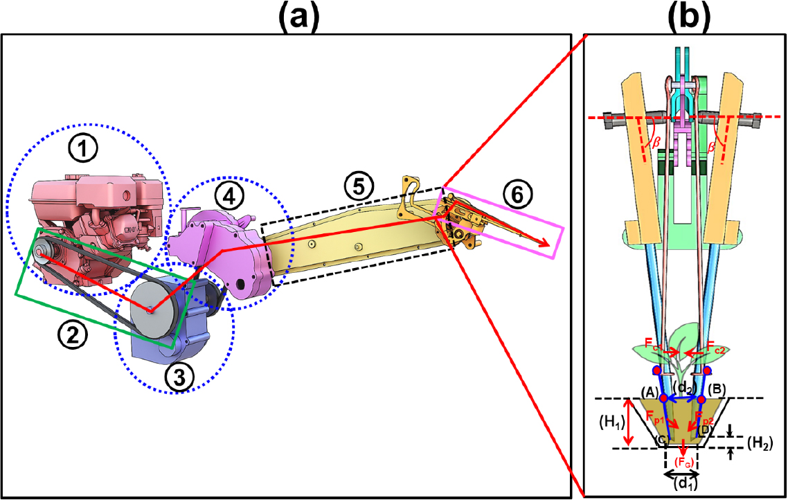
Fig. 3.
(a) Power transmission path in the proposed seedling-picking device: (1) engine, (2) belt drive, (3) drive gearbox, (4) auxiliary gearbox, (5) sprocket, (6) gripper; and (b) schematic diagram of the motion of the gripper toward the seedling tray during the seedling-picking process. β represents the upright inclination of the pickup pin along the grasping direction, LAB and LCD denote dimensional parameters of the pickup mechanism, and d1 and d2 are the lengths at the lower and upper sides of the seedling root zone, respectively. H1 indicates the height of the root lump, while H2 is the vertical distance between the picking pins and the tray cell. Δu1 and Δu2 are the lateral distances from the upper and lower picking pin inlets to the hole, respectively, and FG represents the gravitational force.
The relationship for seedling grasping can be expressed by Eq. (1) as follows:
where, and are the side distances from the upper and lower pick-up pin inlets to the hole, respectively, and is the gravity.
The depth of the picking pins within the root lump can be determined as Eq. (2) as follows:
where, is the height of the root lump, while is the vertical distance between the picking pins and the tray cell.
Seedling picking process involves the motion of the gripper from its initial position toward the seedling tray cell, lifting the seedling, and moving it for release into the planting hopper as illustrated in Fig. 4. The seedling picking process begins with the pickup pins gradually closing around the edges of the tray cell to grasp the seedling, while the slider moves linearly to the left along the initial straight path (Fig. 4a). Once the slider reaches the end of this linear path, it transitions to a circular trajectory cantered around the rotational axis of the slider (Fig. 4b1 and b2). During this curved motion, the gripper moves the seedling from the tray (Fig. 4b3), and at the end of the circular path, the gripper opens to release the seedling into the hopper cup of the planting device (Fig. 4b4). After release, the slider returns to its starting position, completing the cycle.
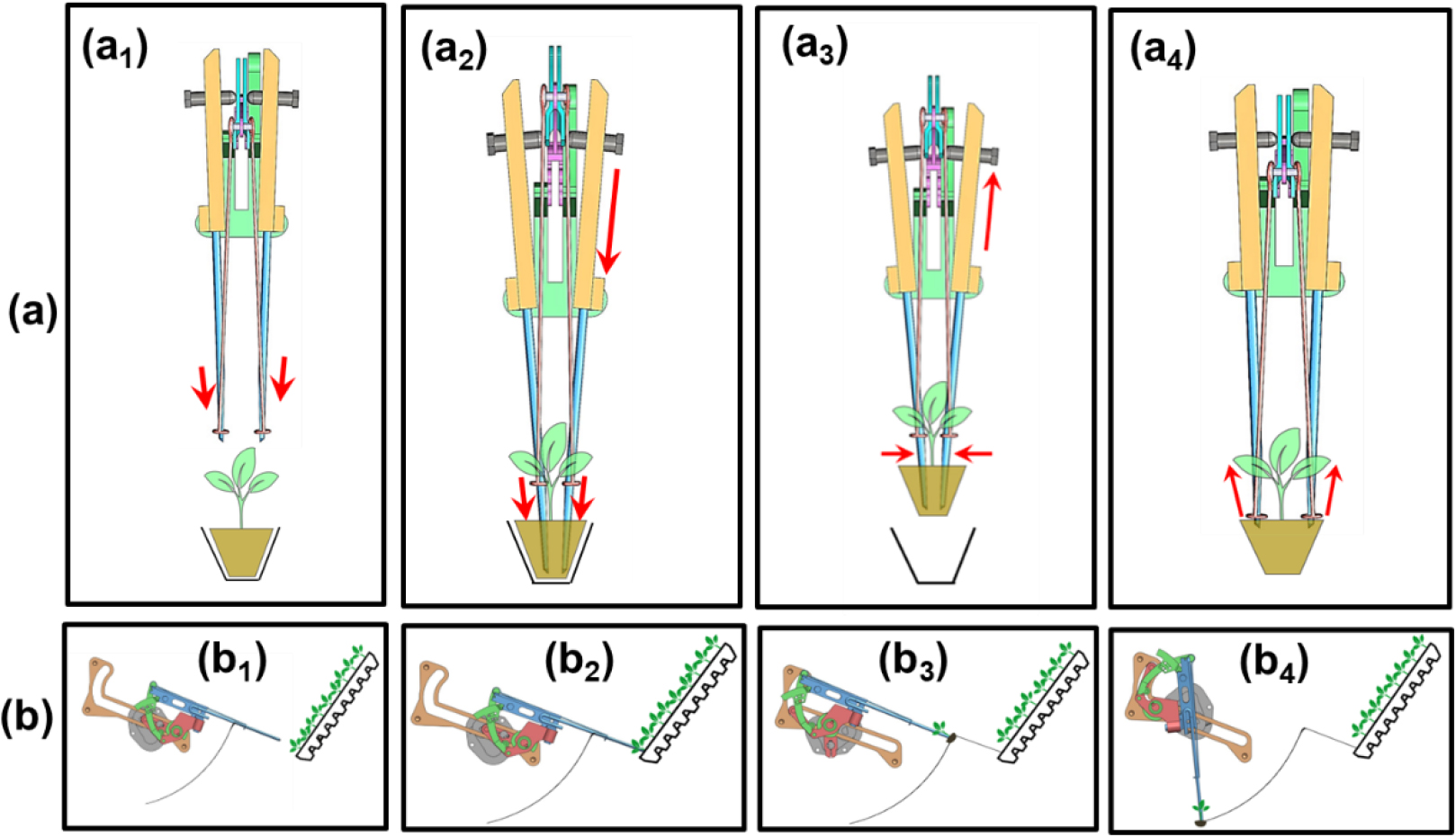
Fig. 4.
Motion of the gripper during the seedling-picking process: (a) sequential positions of the pickup pins: (a1) initial position, (a2) insertion into the seedling root zone,(a3) lifting with the seedling, (a4) releasing the seedling; (b) corresponding motion trajectory of the gripper: (b1) gripper at the initial position, (b2) moving downward toward the root zone, (b3) lifting and transferring the seedling, (b4) discharging the seedling into the planting hopper.
Kinematic modelling using vector loop method
Fig. 5 illustrates the developed vector-loop model of the seedling picking mechanism. The motion of the mechanism was analyzed to determine a suitable combination of linkage elements that achieve the required seedling-picking trajectory. Mathematical equations were derived using a vector-loop approach based on the lengths of the interconnected bar links. The gripper position is controlled by a set of mechanical elements, including the sliding slot link, the opening and closing link, the crank link, and the rotary gearbox link. The resulting trace path depicts the operational movement of the seedling-picking mechanism beginning with the gripper extracting the seedling from the tray at point (T), transporting it along the trajectory, and finally releasing it into the planting hopper at point (H).
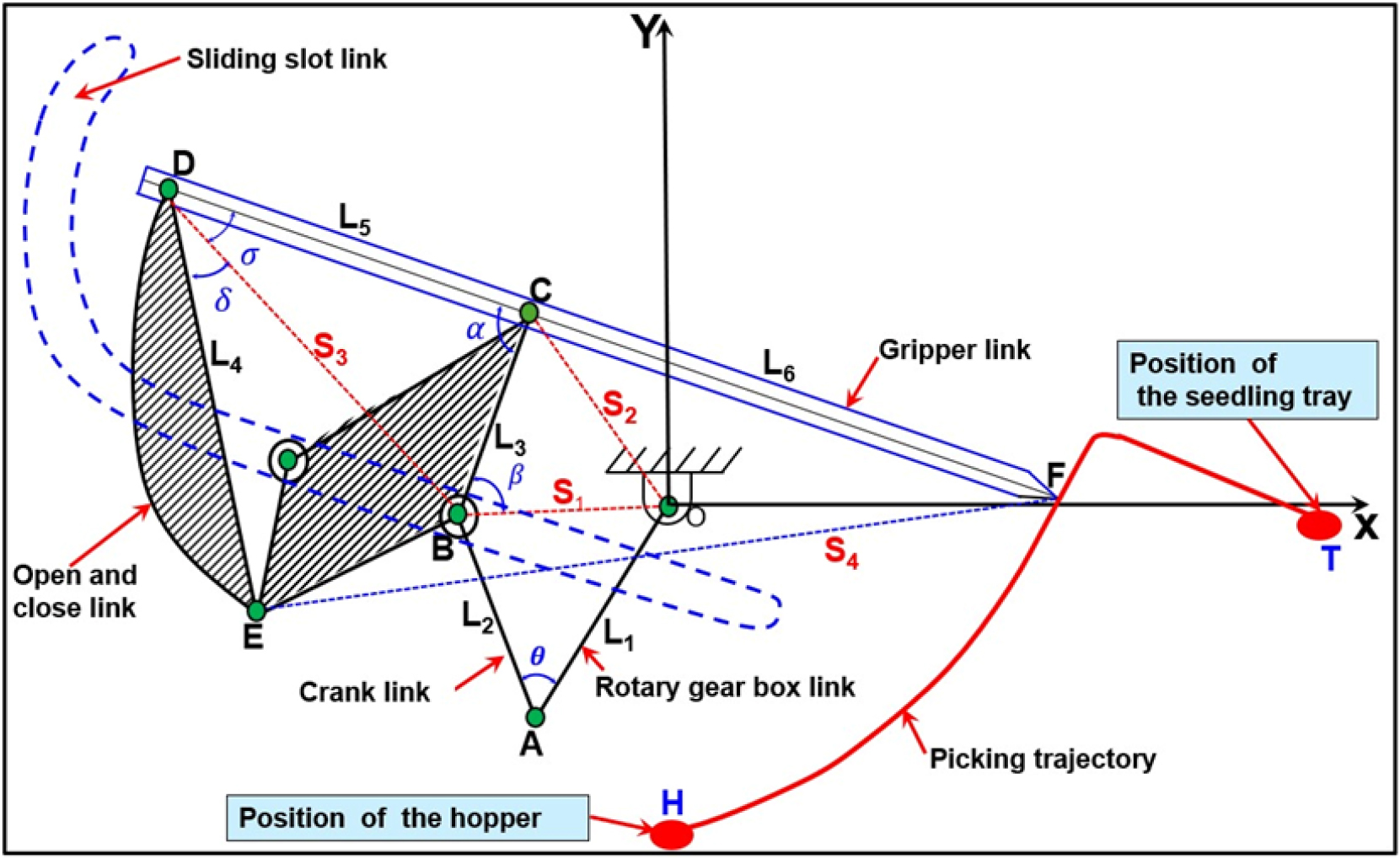
L1, L2, L3, L4, and L5 represent the lengths of the rotary gearbox link, crank link, sliding link along the BC periphery, and the open/close link (ED), respectively. L5 and L6 denote the lengths of the gripper arms DC and CF. S1, S2, S3, and S4 represent the relative distances OB, OC, BD, and EF, respectively. θ is the angle with respect to S1 in triangle ∆OAB. β is the angle with respect to S2 in triangle ∆OBC, α is the angle between the sliding link and the grippers, σ and δ are the angles that together form the opposite angle of S4 in triangle ∆ED. The length of the links and angles formed in the motion vector loop of the gripper can be calculated using Eqs. (3), (4), (5), (6) as follows:
At the Vector loop O → A → B → C → O: Main closed loop
At the Vector loop: B → E → D → C → B: Gripper open and close mechanism
At vector loop O → C → D → F → O: Gripper link and picking path
The dimensions and combinations of the bar links were applied to the mathematical model of the transplanting mechanism to obtain the corresponding values of gripper velocity and acceleration. These kinematic parameters were derived from the first and second derivatives of the vector loop equations. Accordingly, Eqs. (4), (5), (6) were used to compute the velocity and acceleration of the proposed seedling-picking mechanism in the X and Y directions, as detailed in Eqs. (7) and (8) as below:
Simulation and validation procedures
A kinematic simulation of the proposed seedling-picking unit, which transfers seedlings from the tray cells to the planting hopper, was performed to validate the developed mathematical model and to identify an optimal linkage configuration for ensuring a reliable and safe transplanting path. Various simulations involving different gripper lengths and base heights were carried out using a commercial software (SOLIDWORKS, 2018). These trials aimed to determine the suitable gripper positioning and associated kinematic characteristics that satisfy the functional requirements of the pepper seedling-picking mechanism. During the simulation process, eight trials were carried out by varying gripper lengths between 150 mm and 200 mm, and base heights between 15 mm and 30 mm, to determine the optimal gripper position and motion trajectory. In addition, ten separate simulations were conducted with motor speeds ranging from 18 to 36 rpm to evaluate the maximum velocity and acceleration needed for smooth picking, holding, and transferring of the seedlings. To validate the simulation results, a triaxial accelerometer (PCB Piezotronics, 2012) was installed at the tip of the gripper to record acceleration data. The signals were acquired through a signal processing commercial software (National Instruments, 2018), which interfaced with a four-channel signal acquisition module (National Instruments, 2012) and an eight-slot USB data acquisition chassis (National Instruments, 2023). Data were collected at a sampling rate of 1,000 Hz over 10 second intervals. Velocity was calculated by numerically integrating the recorded acceleration signals. The peak linear velocity and acceleration of the picking unit were analyzed at a motor speed of 24 rpm. The motion trajectory of the gripper was verified using open-source video tracking software applied to slow-motion footage recorded at 1,280-pixel resolution and 24 frames per second. Table 1 presents the parameters considered in the kinematic simulation.
Table 1.
Kinematic simulation parameters.
| Fixed parameter | Position of tray cell |
| Size of the fixed slot, slider, and connecting link | |
| Variable parameters | Size of the gripper (base height and length) |
| Rotational speed |
To evaluate the performance of the seedling picking mechanism, field test was conducted using 12 plastic trays (6 × 12 seedling cells per tray). To verify the growth characteristics of the seedlings used in the experiment, a random selection of seedlings was measured for height and stem diameter using a steel tape and a digital caliper, respectively, as shown in Fig. 6.
The performance of the seedling picking device was evaluated based on the condition of seedlings extracted from the tray cells and transferred to the planting hopper. Damaged seedlings refer to those that were physically harmed during the picking process as shown in Fig. 7. The damage rate (%) was calculated using Eq. (9) as follows:
where, : damage rate (%)
: number of damaged seedling
: total number of transplanted seedling
Results and Discussion
Position of the gripper during the seedling transplanting process
Position of the gripper during the seedling transplanting process was evaluated at two specific points: the picking point on the seedling tray and the release point into the planting hopper. Fig. 8 presents simulation trials that demonstrate the position of the gripper at both stages, and in each trial the trajectories of the gripper were presented in Fig. 9. Each trial corresponds to a unique combination of gripper length and base height. Positions labeled (a1) to (a8) represent the gripper during the picking phase, while positions (b1) to (b8) indicate the gripper position during the release phase at the mouth of the planting hopper. The yellow bullet indicates the location of the tray cell, the blue bullet marks the mouth of the planting hopper, and the black dot at the center of each bullet represents the seedling position. The appropriate position of the gripper at the picking point is achieved when the endpoint of the gripper is precisely aligned with the center of the yellow bullet, within the black dot. Similarly, the appropriate position of the gripper at the release point is achieved when the endpoint of the gripper, located at the center of the blue bullet, aligns with the black dot.
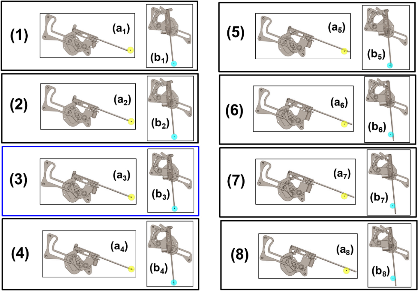
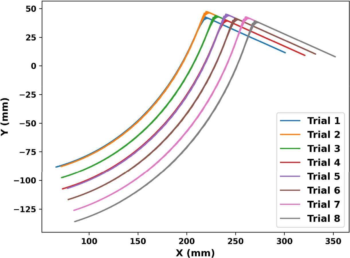
Table 2 presents the simulated gripper positions based on different gripper lengths and base heights. In Trial 3, the coordinates 311.70 mm on the X-axis and 12.59 mm on the Y-axis were identified as optimal for accurate entry into the tray cell. These values, associated with a gripper length of 160 mm and a base height of 20 mm, allowed for successful seedling pickup without causing damage or mechanical stress. Any deviation from these dimensions led to misalignment of the pickup pins, which increased the risk of damaging the seedling or reduced grasping efficiency due to incorrect insertion angles. The gripper followed a curved linear trajectory from the tray cell to the release point. The X-axis values increased progressively from 65.98 to 85.28 mm across the trials, indicating forward movement. Simultaneously, the Y-axis values decreased from -88.36 to -135.97 mm, reflecting a downward displacement during the release phase. Trial 3 was identified as the optimal configuration for seedling release, with coordinates of 71.83 mm on the X-axis and -97.71 mm on the Y-axis, ensuring accurate placement and minimizing mechanical stress while preventing damage to the seedling.
Table 2.
Analytical positions of the gripper at the seedling picking and release points.
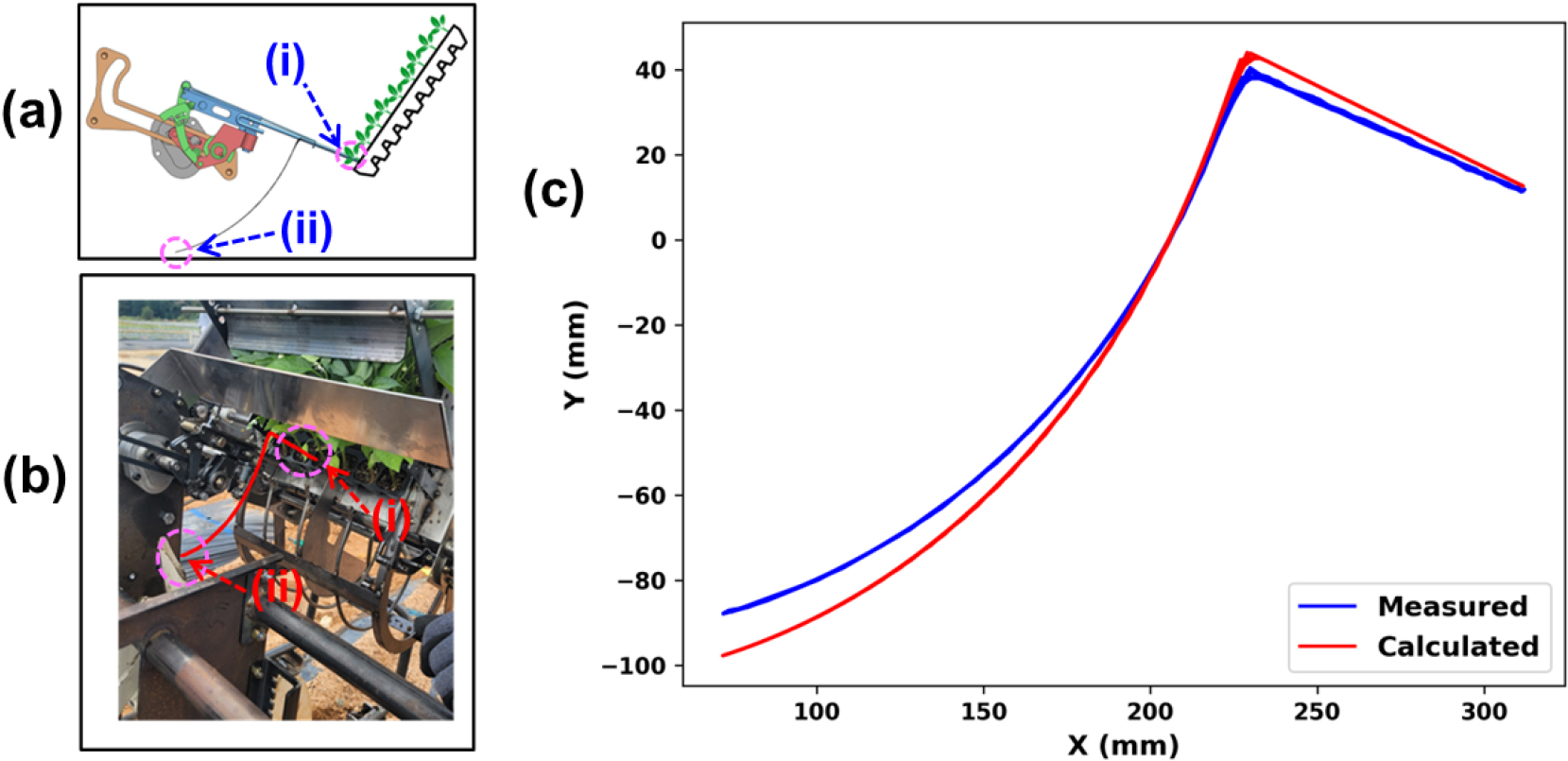
A comparison between the calculated and experimentally measured gripper positions at the seedling picking and release points demonstrates a strong agreement in motion trends. During the picking motion toward the seedling tray cell, the calculated position reached 311.70 mm along the X-axis and 12.59 mm along the Y-axis, while the experimental measurement recorded 337.46 mm on the X-axis and 38.92 mm on the Y-axis. For the release motion toward the planting hopper, the calculated values were 71.83 mm on the X-axis and -97.71 mm on the Y-axis, compared to the experimental values of 75.79 mm and -102.95 mm, respectively, as shown in Table 3 and Fig. 10. Minor deviations, particularly in the Y-direction, are likely due to mechanical tolerances or structural flexibility not considered in the simulation. Overall, the results confirm that the simulation reliably represents the actual motion of the gripper.
Table 3.
Comparison of calculated and measured gripper positions.
Velocity and acceleration of the gripper
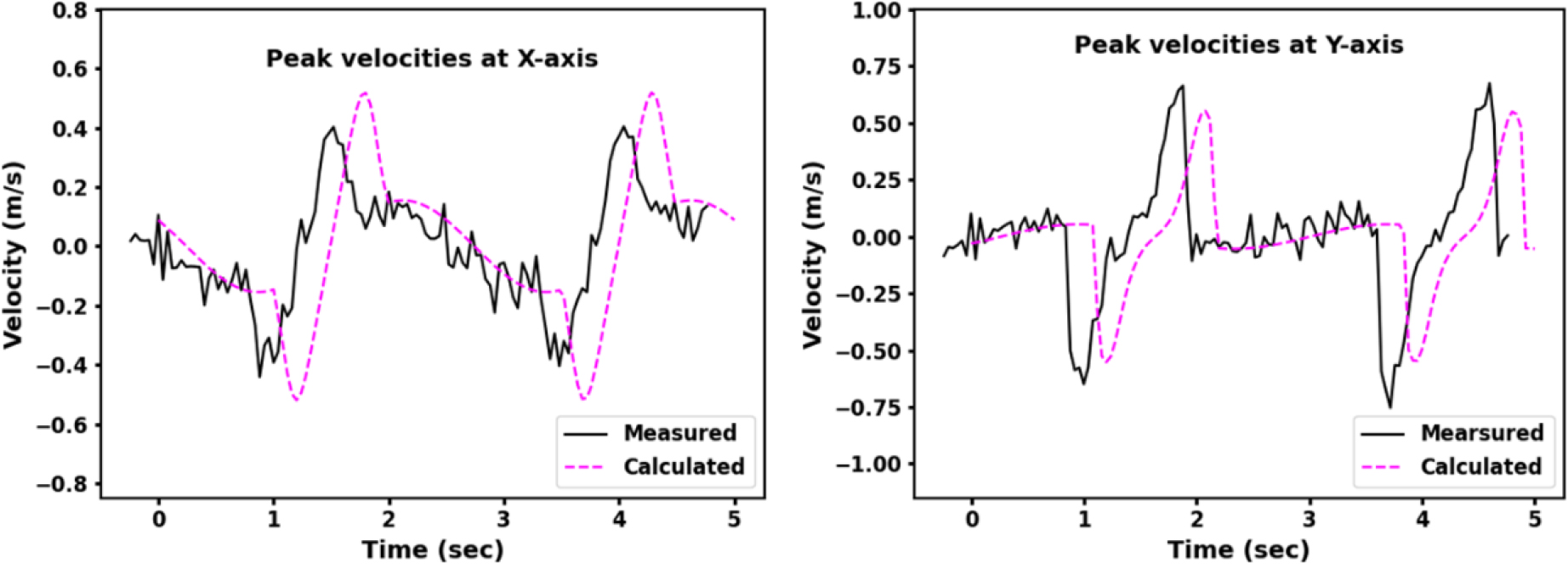
The velocity and acceleration of the gripper significantly affect both the accuracy of seedling placement and the mechanical stress exerted during the transplanting process. The maximum peak velocity and acceleration were calculated using ten simulation trials at motor speeds ranging from 18 to 36 rpm, which showed that both values increased proportionally with the rotational speed. The calculated velocity ranged from -0.52 to +0.51 m·s-1 along the X-axis and from -0.60 to +0.60 m·s-1 along the Y-axis. Experimental measurements showed ranges of -0.45 to +0.50 m·s-1 on the X-axis and -0.64 to +0.70 m·s-1 on the Y-axis. At 24 rpm, the gripper demonstrated optimal dynamic performance, recording peak velocities of -0.52 m·s-1 along the X-axis and -0.60 m·s-1 along the Y-axis, both well below the critical threshold of 0.8 ms-1 recommended to prevent mechanical damage to seedlings (Ye et al., 2020). These results confirm that the transplanting process of the designed prototype maintained consistent and safe velocity dynamics across the tested speed range compared with previously reported findings.
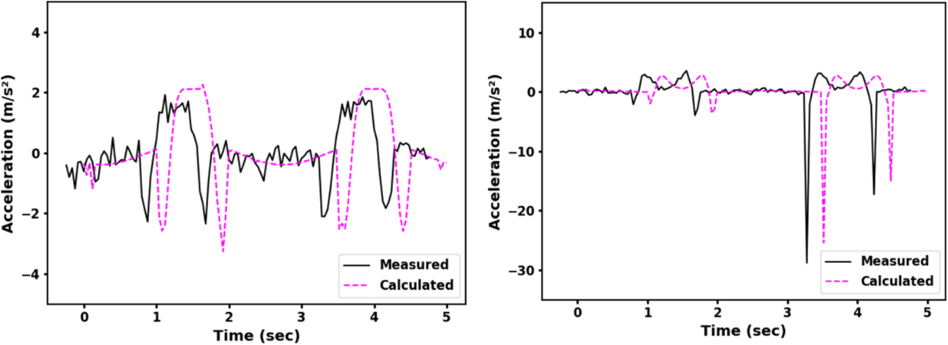
Similarly, the calculated acceleration values ranged from -3.26 to +2.26 m·s-2 along the X-axis and from -25.41 to +2.76 m·s-2 along the Y-axis, while experimental measurements ranged from -2.37 to +2.19 m·s-2 along the X-axis and from -28.94 to +3.61 m·s-2 along the Y-axis. At 24 rpm, the gripper exhibited peak accelerations of -3.26 m·s-2 along the X-axis and -25.41 m·s-2 along the Y-axis both within the maximum allowable limit of 30 m·s-2, which is considered safe to prevent root ball disintegration and ensure transplanting reliability (Islam et al., 2020). This would offer basis evidence to demonstrate prevalence of the proposed design. However, at motor speeds exceeding 26 rpm, the acceleration in the Y-direction consistently surpassed the 30 m·s-2 threshold, potentially increasing the risk of root ball breakage and mechanical injury to seedlings. These observations underscore the importance of regulating motor speed during the transplanting process to ensure biomechanical safety and achieve optimal transplanting performance. Tables 4, 5, 6 present the simulation results of the calculated velocity and acceleration of the gripper at various motor speeds, along with the comparisons between the calculated and measured peak velocities and accelerations, respectively. Figs. 11 and 12 present the comparison between the calculated peak velocities and accelerations of the gripper.
Table 4.
Simulation results of the calculated velocity and acceleration.
Table 5.
Comparison of calculated and measured peak velocities.
| Direction | Calculated (m·s-1) | Measured (m·s-1) |
| X- component | -0.52 to +0.51 | -0.45 to +0.50 |
| Y-component | -0.60 to +0.60 | -0.64 to +0.70 |
Table 6.
Comparison of calculated and measured peak accelerations.
| Direction | Calculated (m·s-2) | Measured (m·s-2) |
| X- component | -3.26 to +2.26 | -2.37 to +2.19 |
| Y-component | -25.41 to +2.76 | -28.94 to +3.61 |
Evaluation of seedling picking performance
To evaluate the operational reliability and gentleness of the seedling transplanting mechanism, a seedling picking test was conducted using twelve (6 × 12-cell) trays of pepper seedlings, each containing 72 mature seedlings. Table 7 presents the number of visibly damaged seedlings recorded per tray and the quantified damage rate as a percentage. The observed damage rate varied across trays, ranging from 0.0% (Trays 4, 5, 10, and 12) to a maximum of 5.55% in Tray 9, which showed the highest occurrence of seedling injury likely due to subtle local inconsistencies in seedling growth combined with gripper and planting hopper motion. The second-highest damage rate was 4.16% in Tray 3, while most other trays showed damage rates between 1.38% and 2.77%. The overall average damage rate across all trays was approximately 1.71%, with a standard deviation of ±1.78%, indicating a relatively low and consistent level of mechanical disturbance. According to Sun et al. (2016), Damage rates below 5% are considered acceptable in commercial transplanting operations, particularly when the injuries are minor such as leaf tip breakage and do not affect the integrity of the root ball or stem. The results demonstrate that the transplanting gripper mechanism exerted minimal mechanical stress on the seedlings and exhibited performance characteristics aligned with commercial-grade transplanting standards.
Table 7.
Damaged pepper seedlings during the transplanting process.
According to the field observations and the performance test results presented in Table 7, seedling damage and difficulty in achieving optimal timing synchronization between seedling supply and hopper motion were identified.
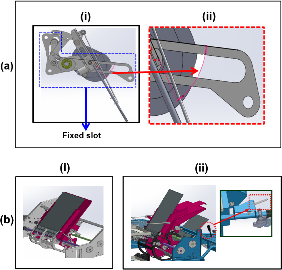
The first issue stemmed from the original discharge slot geometry, which had an excessive seedling extraction angle that caused instability in ejection and led to unreliable discharge performance. To address this, the slot should be redesigned by reducing the extraction angle shown in Fig. 13a(ii).
Also, the field operation remarked on the lack of field-operable tray inclination adjustment. To solve this, a manual adjustment lever should be introduced to allow operators to make on-site tray angle adjustments, enabling better alignment with the hopper motion and improving the timing of seedling delivery as shown in Fig. 13b(ii). This adaptability not only improves planting precision but also reduces seedling misalignment and damage during insertion. Together, these targeted design changes might directly respond to the key functional deficiencies observed in field trials and contribute to a more efficient, resilient, and user-adaptable transplanting mechanism.
Conclusion
A comprehensive kinematic analysis and field performance test were conducted for the proposed seedling picking mechanism integrated into a 3.4 kW walking-type automatic pepper transplanter. Through vector-loop-based modeling, simulation trials, and field experimental tests, optimal operating parameters for precise and gentle seedling handling were established.
A gripper length of 160 mm, a base height of 20 mm, and a motor speed of 24 rpm yielded the most stable and accurate picking trajectory. The gripper reached peak simulated positions of 311.70 mm along the X-axis and 12.60 mm along the Y-axis at the seedling picking point, and 71.84 mm (X-axis) and -97.71 mm (Y-axis) at the planting hopper. Experimental validation showed close agreement, with measured positions of 337.46 mm and 38.92 mm at the picking point, and 75.79 mm and -102.95 mm at the release point, confirming the reliability of the simulation model.
Calculated gripper velocities ranged from -0.52 to +0.51 ms-1 along the X-axis and from -0.60 to +0.60 ms-1 along the Y-axis, while acceleration values varied from -3.26 to +2.26 ms-2 (X-axis) and from -25.41 to +2.76 ms-2 (Y-axis). These results were consistent with experimental findings, all remaining within the biomechanical safety thresholds of 0.8 ms-1 for velocity and 30 ms-2 for acceleration particularly in the Y-direction, which is more critical for maintaining root stability during transplanting.
Field tests using twelve trays of pepper seedlings yielded an average seedling damage rate of 1.73 ± 1.78%, well below the commercial damage threshold of 5%. Trays 9 and 3 exhibited slightly higher damage rates (5.55% and 4.16%, respectively), likely due to localized variations in seedling density and structure, which affected gripper clearance and alignment. The experimental results confirmed that the mechanism imposed minimal mechanical stress on the seedlings during the extraction process, validating its suitability for commercial-scale operations. Overall, the findings demonstrate that the developed mechanism provides efficient seedling transplantation, although the slot geometry at its current angle causes inconsistent synchronization between seedling supply and hopper motion, leading to seedling damage. Future research should focus on redesigning the fixed slot and introducing a tray adjustment lever to improve smooth seedling delivery, which should then be tested in the field to verify the performance of the picking device.
