

Introduction
Materials and Methods
Overview and working principle of sliding-type picking mechanism
Modelling requirements of automatic seedling picking mechanism
Theoretical analysis
Simulation of the sliding pin and bar picking mechanism
Results and Discussion
Position of the end-effector
Trajectory of the end-effector
Velocity and acceleration of the end-effector
Conclusion
Introduction
Pepper (Capsicum annuum L.) is a horticulture crop grown for multiple purposes, including human consumption and biological functions (Syamilah et al., 2022). Pepper is a source of provitamins A, E, and C rich in carotenoid and phenolic compounds with a distinct aromatic flavor, which is critical for metabolism and disease prevention (Younes and Mustafa, 2023). Pepper belongs to the Solanaceae family and the genus Capsicum, which is composed of 31 species. Five common domestic Solabaceae pepper species are C. annuum, C. baccatum, C. chinense, C. frutescens, and C. pubescens, among them C. annuum is the most commercialized (Medalcho et al., 2023).
Global pepper production was estimated to be 520,000 tons compared to a demand of 530,000 tons in 2022/2023, and Vietnam was the top-producing country with around 205,000 tons, followed by Brazil with 112,000 tons and India with 64,000 tons (Nedspice, 2023). Labor scarcity has led to a notable decline in pepper production and areas under cultivation in several countries, resulting in a production shortfall for consumers (Gobie, 2019). South Korea experienced a notable decrease in pepper production and cultivation between 2013 and 2021, with yields falling from 117.8 thousand tons to 92.8 thousand tons and from 45.4 thousand hectares to 33.4 thousand hectares of land (KOSTAT, 2022). In 2022, pepper mechanization rates in South Korea were 99.6% for tillage, 0% for planting, 87.8% for pest control, and 0% for harvesting (RDA, 2023). A feasible way to address the labor shortage and increase pepper production would be to use transplanters, which can plant 500 to over 1,000 seedlings per hour as opposed to 100 to150 seedlings when transplanting by hand (Muragi and Sajjan, 2019; Periasamy et al., 2021; Khater et al., 2023).
The pepper transplanter consists of extracting the seedling from the nursery tray in a repetitive way, transfers it to a conveying mechanism, releases it onto a planting device, and then plants it in the soil (Habineza et al., 2023). The picking mechanism is an essential part of the planting process that moves the maximum amount of root mass of the seedling without harming the roots, stems, or leaves and ensures the proper planting trajectory, which directly impacts crop growth (Zhao et al., 2020; Periasamy et al., 2022). A successful seedling extraction process considers the agronomic characteristics of the seedling and the mechanical design of the picking component (Han et al., 2023a). The picking angle toward the seedling tray and the moisture content of the seedling medium enable the smooth picking mechanism (Zhang et al., 2022). The necessary picking angle with respect to the tray cell must be smaller than the taper of the tray cell, and the moisture content level of the seedling medium must be controlled as low-moisture lumps are easily crushed, while wet root lumps are soft and may make it difficult for the picking component to grasp the seedlings and hold onto the surrounding soil (Liu et al., 2019). According to Ryu et al. (2001), the ideal values of the root lump moisture content ranged from 55% to 65%, with a success ratio of more than 90%. Mao et al. (2014) developed a pincette-type pick-up device for automatic transplanting seedlings; the optimal root lump moisture content ranged from 55% to 60% with a success ratio of 90.71%. Companies developed the two types of seedling pick-up devices for vegetable transplanters that are the most popular in Korea and Japan. One type extracts the seedling from the cell by using a complex mechanism consisting of a slider, cam, and links to create a cross path, whereas the other type moves the pick-up pin in an open, counter-clockwise loop towards the lower part of the cell surface (Sivakumar and Durairaj, 2014). The purpose of this study was to conduct the kinematic analysis of the sliding-type automatic picking mechanism of a pepper transplanter prototype through a theoretical simulation analysis for efficient seedling transplanting.
Materials and Methods
Overview and working principle of sliding-type picking mechanism
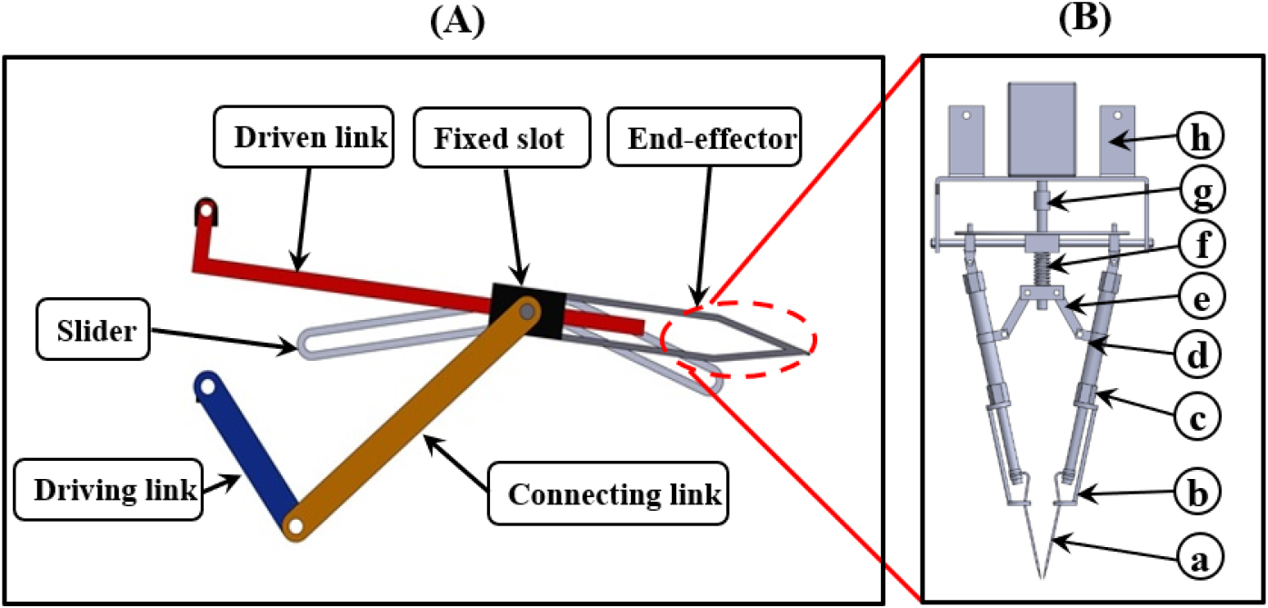
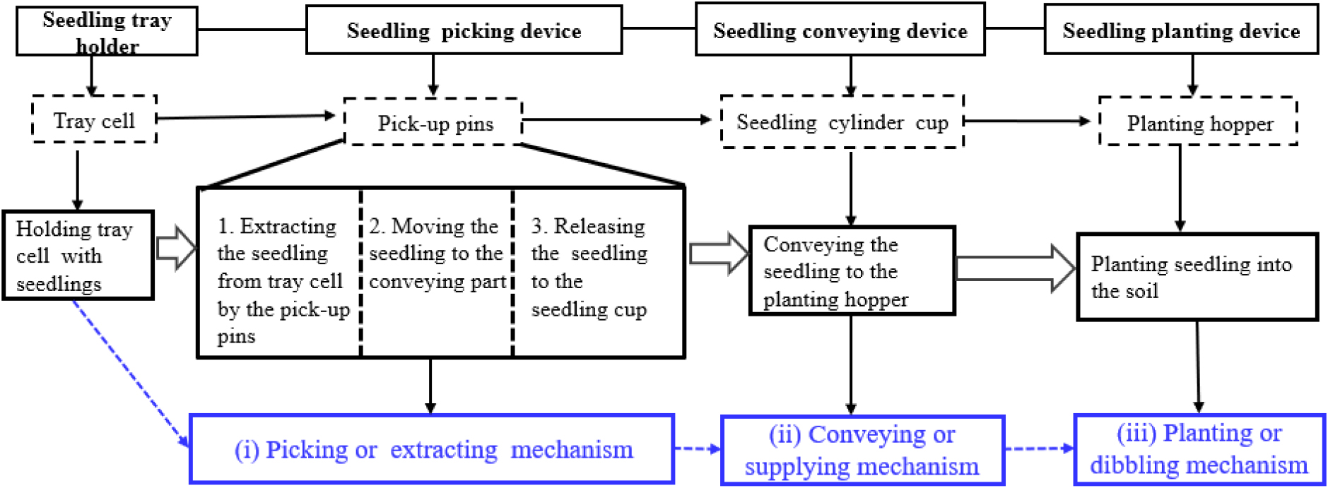
Three-dimensional (3D) model of a pick-up device was designed to evaluate the automatic seedling picking mechanism. The entire picking mechanism consisted of driving link, connecting link, driven link, fixed slot, slider, and an end-effector holding pins that worked by sliding motion to move the seedlings from the cell tray and releasing them into the conveying section. The planting hopper received the seedlings from the cylinder cups of the conveying mechanism, planting them in the soil and covering the surrounding area of the planted seedling. The whole transplanting mechanism worked in a repetitive, revolutionary way, following the engine operation and transplanter setting. Figs. 1 and 2 illustrate the major parts of the automatic pepper transplanter prototype and the description of the working principle, respectively.
Modelling requirements of automatic seedling picking mechanism
Seedling picking components
The picking mechanism was modeled based on the agronomic traits of the pepper seedling and mechanical features of the picking components to ensure a successful seedling transplanting while avoiding damage to the root, stem, or leaves. The pepper seedling should be grown for 45 days in a controlled moisture content of the seedling medium to acquire the necessary height, stem diameter, and leaf area to enable the smooth picking process (Iqbal et al., 2022). The seedling picking components should be flexible for angle adjustments toward the seedling tray to ensure the survival rate and minimize bruise damage when picking the seedling (Han et al., 2023b). The designed picking component was 5-bar linkage type corresponding to a driving link, a driven link, a connecting link, a slider, and an end-effector. The end-effector was fastened with a pair of pins that extracted the seedling from the growing medium to gently grasp, hold, lift, and release the seedling into the cylinder cup of the conveying device by the sliding motion. The overall dimension of the tray cell considered was (280 mm × 540 mm) arranged into 6 × 12 (72 seedlings), with the cell dimension being 45.8 mm in height, 40 mm on the top, and 20 mm at the bottom. The cylinder cup of the conveying device measured 57 mm in height, 27 mm in diameter at the top, and 18 mm in diameter at the bottom. Fig. 3 illustrates the seedling picking components.
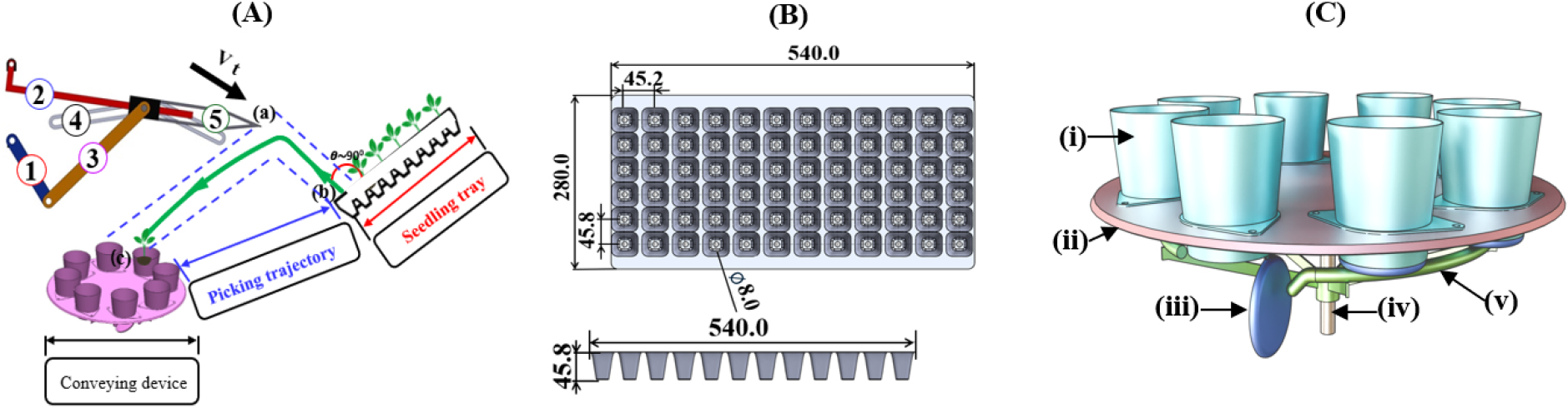
Fig. 3.
(A) Structure of automatic seedling pick-up mechanism: (a) Initial position of end effector, (b) Seedling extraction point, and (c) Seedling release point; (1) driving link, (2) driven link, (3) connecting link, (4) slider, and (5) end-effector; (B) Seedling tray, and (C) Seedling conveying mechanism: (i) cylinder cup, (ii) rotating plate, (iii) cylinder cup cover, (iv) shaft, and (v) base ring.
Seedling picking process
Transplanting process is initiated when the engine starts and the transplanting throttle lever engaged, which transmits the power to the end-effector via the driving, driven, and connecting links. The tractive action of the pivot arm enabled the connecting piece to push the pick-up pins in the direction of the seedling, allowing them to enter the tray cell wall through the root lump. The spring tension forced the coupling ring to deflate and contract, which permits the pivot arm to close for pulling the seedling from the growing tray cell and open to release the seedling to the conveyor section. The gasket of the pivot arm modulated the opening to effectively grasp, hold, and release the seedlings. Assuming that the pick-up pins were symmetric, and the root lump was equilateral, the relationship between the pick-up pins and the tray cell for seedling grasping can be calculated as described in Fig. 4A as Eq. (1).
where, , are the corresponding pickup parameter dimensions with and with lengths at the lower side and the upper side of the seedling root zone respectively. and are the side distances from the upper and lower pick-up pin inlets to the hole, respectively, mm.
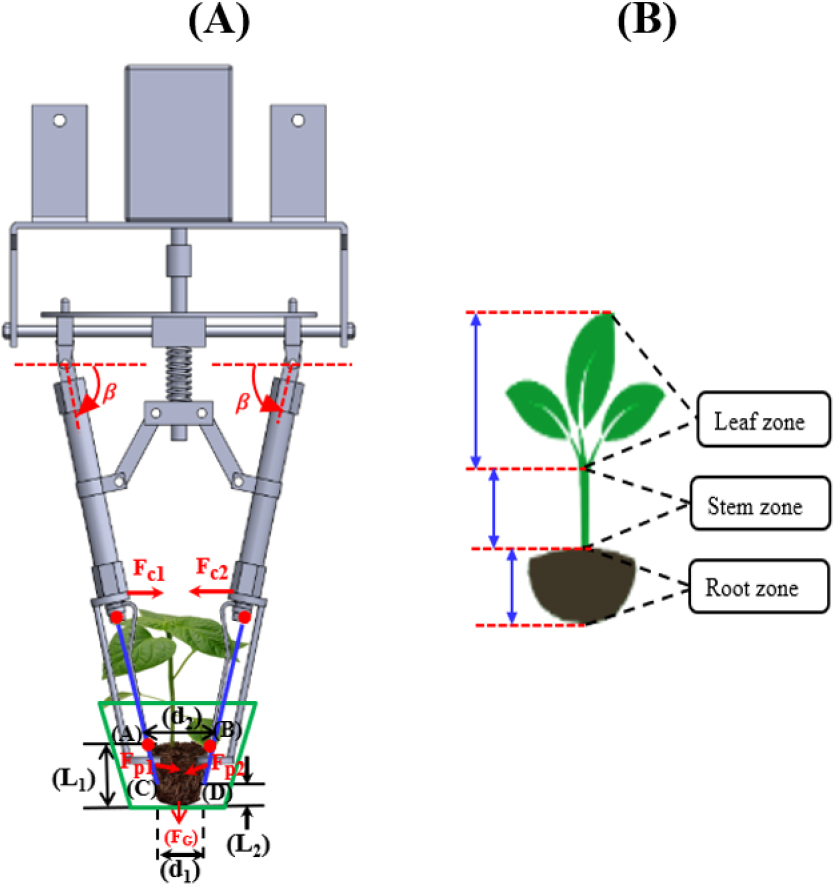
Fig. 4.
(a) Schematic drawing of seedling picking process, and (b) Main parts of the seedling. is the upright inclination of pickup pin along the grasping direction, ( and ) are pickup parameter dimensions with and the lengths at the lower side and the upper side of the seedling root zone, ( and ) are the heights of the root lump and vertical distance from the end of the pick-up pin to the hole bottom, and is the gravity.
The inclination angle of the pick-up pin toward the seedling picking tray was set as , and the pick-up pins penetration depth can be calculated as Eq. (2).
where, is the height of the root lump, is the vertical distance of the pick-up pins to the tray cell bottom, and is the angle of the seedling picking inclination, and represented the depth of picking pin penetration.
Seedling picking trajectory
The trajectory of seedling picking involves the motion of the end-effector from the initial position towards the seedling cell tray forming an angle close to 90°, lifting, and moving the seedling to the release point on the conveying device. When picking up seedlings, the pick-up pins opening should always be smaller than the bottom width and top of the tray cell to squeeze and hold the root lump firmly at the maximum penetration depth (Habineza et al., 2024). Pick-up pins gradually close within the cell edges to move the seedling from the tray when the slider moves to the left along the same straight path as the initial position end-effector. When the slider reaches the end of the straight-line path, it switches to the circular path, which is the rotational center of the driven link. The seedling is released from the end-effector into the conveying device at the end of the circular path, where the seedling is dropped into the cylinder cup and the slider returns to the initial position, forming a curved trajectory. Fig. 5 describes the motion of the end-effector and position of pick-up pins to generate the seedling picking trajectory.
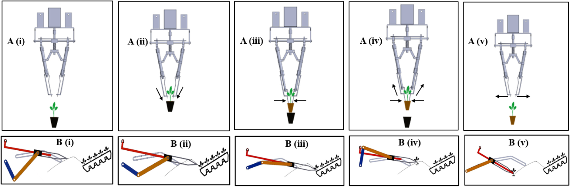
Fig. 5.
Seedling picking mechanism steps: (A, B) Position of pick-up pins and motion trajectory of the end-effector, respectively: (i) End-effector at initial position, (ii) End-effector moving toward the seedling tray, (iii) pick-up pins enter picking the seedling root at extraction point, (iv) Picked seedling for transplanting, and (v) Seedling at discharge point.
Theoretical analysis
Position analysis of the end-effector
The motion of the sliding pin and bar picking mechanism was investigated to select the appropriate link combination of the mechanism that gives the required seedling picking trajectory. The mathematical equations were developed based on length combination of bar links using a vector loop-model. Driving link, driven link, connecting link and fixed link controlled the position of the end-effector. The trace path trajectory reflected the motion of the seedling-picking mechanism, where the end-effector extracts the seedling from the cell tray at point (E), carries it, and drops it at the conveying unit at the point (D). Fig. 6 represents the developed vector-loop model of the transplanting mechanism.
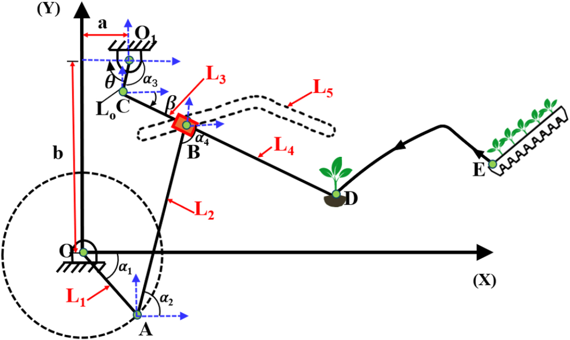
where, , , , and are the lengths of the driving link, the connecting link, the driven link, the end-effector, and the fixed link, respectively. , , , , , are the angles with respect to the horizontal for the driving link, connecting link, driven link and for the end effector, and is the angular velocity of the links and velocity. The vector loop equations for the end-effector motion of the sliding pin and bar mechanism are shown as Eqs. (3), (4), (5), (6), (7).
At point A,
At point B,
At point C,
At point D,
Velocity and acceleration of the end-effector
The length and size combinations of the bar links were substituted in the mathematical model of the transplanting mechanism to calculate the corresponding values of velocities and acceleration of the end effector. Velocity and acceleration can be calculated using the first- and second derivatives of the vector loop equations. Therefore, Eqs. (8) and (9), can be used to calculate the velocity and acceleration of the suggested seedling picking mechanism in the X and Y directions, respectively as Eqs. (8) and (9).
where, is the angular velocity of the links and the velocity and acceleration of the fixed link () are zero.
Simulation of the sliding pin and bar picking mechanism
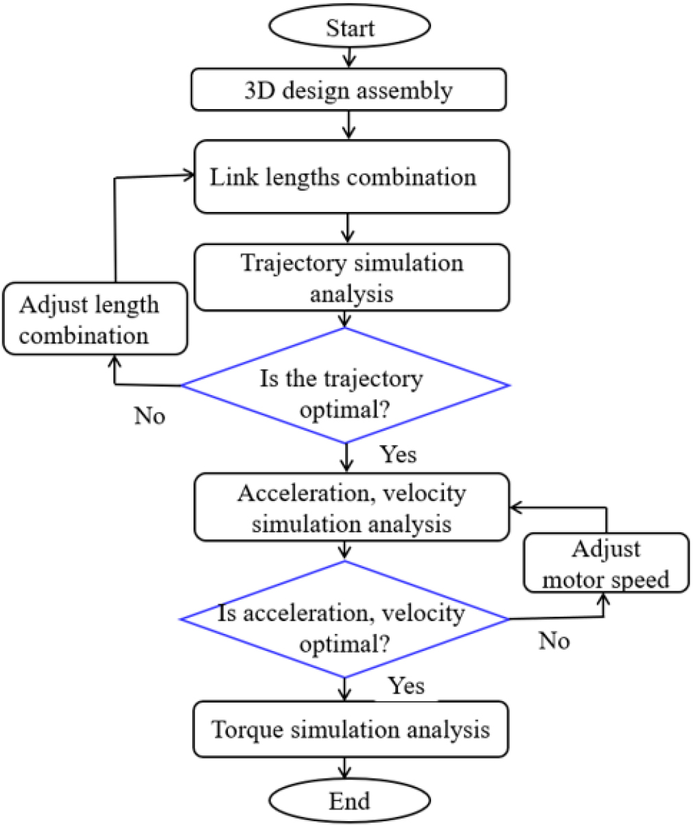
A kinematic simulation of the sliding pin and bar-picking mechanism was carried out to verify the mathematical model and select the optimal link combination that produced the necessary seedling transplanting trajectory. A 3D model of the picking mechanism was developed using a commercial software (Dassault Systems SolidWorks Corp., USA) to determine the kinematic parameters of the proposed picking mechanism. The software was used to ascertain the impact of end-effector kinematic characteristics (position, velocity, acceleration, torque, and links length) for successful seedling transplanting. During the simulation, ten link combination trials was conducted to select the optimal length links combination for smoothly moving the seedling from the cell tray to the conveyor mechanism without harming the seedling. Six rotational speeds (10, 20, 30, 40, 50, and 60 rpm) were also considered to evaluate the input motor torque needed to drive the picking device. The simulation could verify the results of the theoretical analysis, the design of the mechanism, and the trajectory that satisfies the requirements for seedling transfer. The simulation made assumed that the picking device cover and other components were made of alloy steel 102. The physical properties of steel alloy included density, modulus of elasticity, Poisson’s ratio, yield strength, with 7.85 × 10³ kg·m-3, 207 GPa, 0.3, and 210 MPa, respectively. Fig. 7 illustrates the flowchart of kinematic simulation using a commercial software.
Results and Discussion
Position of the end-effector
Motion of the end-effector toward the seedling tray and from the cell tray to the seedling release point was considered ideal distance from initial position of the end-effector and tray cell as well as the ideal distance at seedling release point for safe seedling transplanting. The input motion was applied to the driving link from the engine, which was distributed to both the drive gearbox and the auxiliary gearbox through the sprocket drive. The power is then supplied to the driven link through the connecting link and channelled to the end-effector via the slider. To select the appropriate position of the end-effector, ten simulation trials was conducted at a constant motor speed of 30 rpm and constant length of fixed link of 140 mm. The simulation results were displayed in Fig. 8A, where the yellow mark points indicated the position of the seedling in the tray cell. The optimal distance between the initial position of end-effector and seedling tray to the seedling release point was 88.04 mm, and 131.70 mm, respectively. Below or above 88.04 mm distance from end-effector to the seedling tray cell, the end-effector could not pick up the seedling. Table 1 illustrates the simulation trials distances of the initial position of the end-effector to the seedling tray. Fig. 8 illustrate the simulation positions of the end-effector toward the seedling tray and graphic representation, respectively.
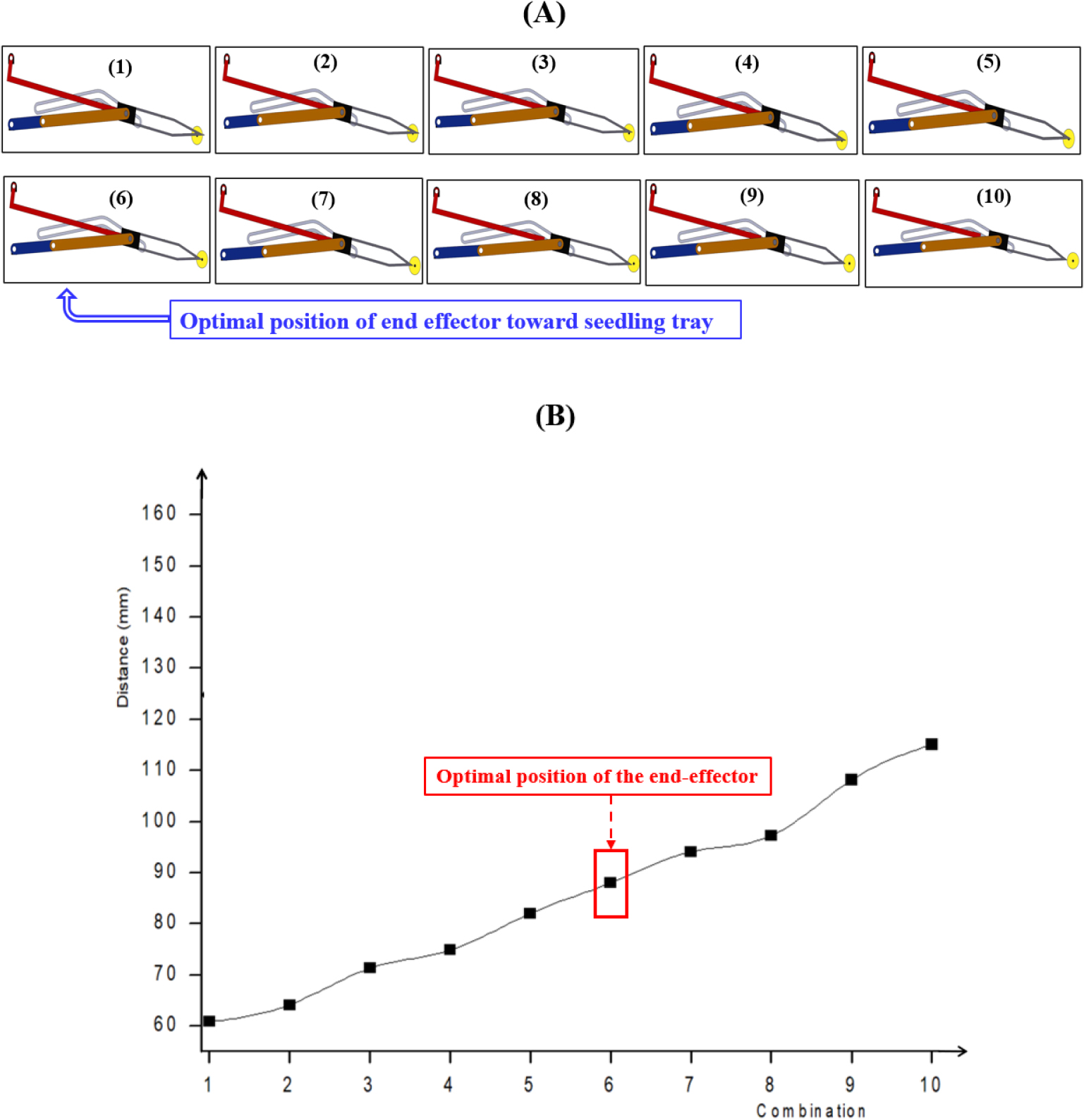
Table 1.
Position of the end-effector toward the seedling tray and seedling release points.
| Trial | 1 | 2 | 3 | 4 | 5 | 6 | 7 | 8 | 9 | 10 |
|
Position of end-effector (mm) | 60.89 | 64.18 | 71.33 | 74.88 | 82.1 | 88.04 | 94.15 | 97.26 | 108.16 | 115.1 |
Trajectory of the end-effector
The seedling picking trajectory was considering the length combination of the picking mechanism components and the location of seedling tray. To select the best length combination, ten simulation trials of different lengths of the driving link, connecting link, driven link, and end-effector was conducted as shown in Fig. 9A. Also, the distance from the initial position of the end-hopper toward the seedling tray and the distance of seedling motion from the tray to the release was evaluated as illustrated in the Table 2. The optimal link length combination was 54 mm, 106 mm, 116 mm, 114 mm, and 140 mm for driving link, connecting link, driven link, end effector and fixed link respectively. The optimal distance between the initial position of the end-effector and seedling tray was 43.66 mm, and the optimal distance from the peak point to seedling release is 88.04 mm while the optimal picking angle was 126.3°. Table 2 represent the results of length links combination trials and the distance between the initial position of end-effector toward the seedling and from seedling tray to the release point. Fig. 9 represents the seedling picking trajectories at different link length combinations.
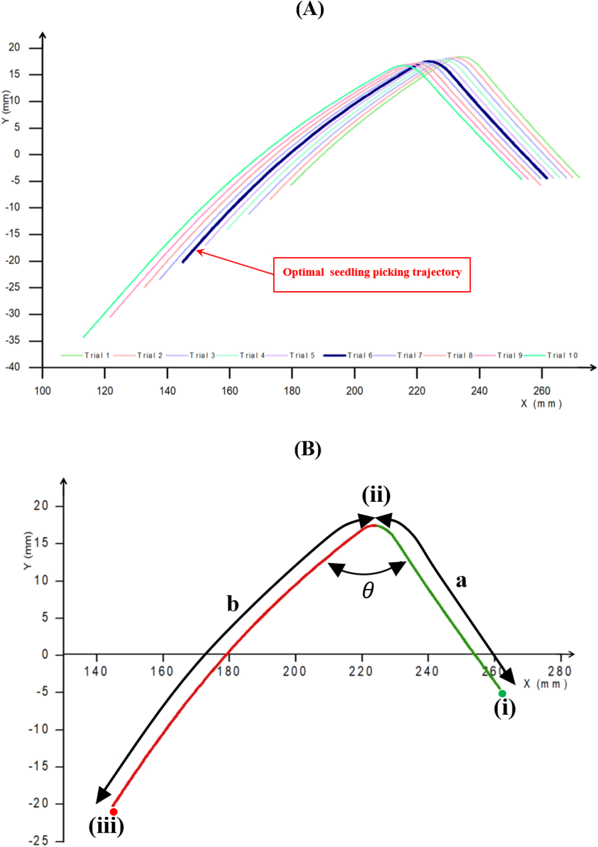
Table 2.
Trials of the picking mechanism link length combinations, distances between the end-effector and the seedling tray (A), and the seedling tray to the discharge point (B).
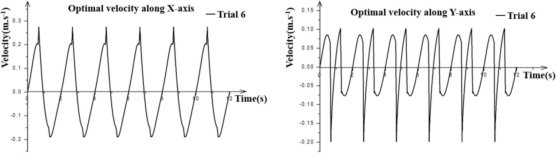
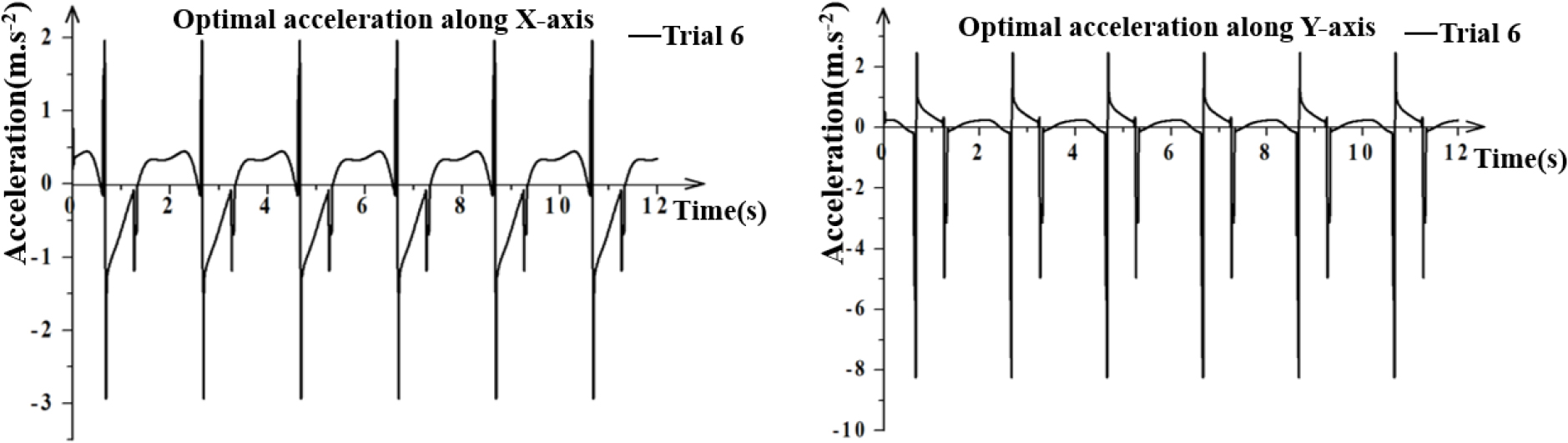
Velocity and acceleration of the end-effector
The kinematic modelling of a seedling picking device was conducted using the simulated motion of pick-up pins, considering the X-Y coordinates to determine the velocity and acceleration as well as the necessary input driving torque. The seedling was moved by the pick-up pins in a counterclockwise direction from the tray cell to the discharge point, forming a peak angle of 126.3° at 30 rpm of driving link speed with the picking rate of 30 seedlings per minute. The peak velocity and acceleration of the end effector in ‘X’ and ‘Y’ directions for appropriate link combination were found as 0.274 m·s-1, 0.199 m·s-1 and 2.94 m·s-2, 8.249 m·s-2 respectively. If the velocity were increased further, then the peak acceleration could not likely be reduced without also affecting the extracting and discharging of seedlings. The seedling was discharged at the peak input driving torque of 2,700 Nm. Table 3 represent the maximum velocity and acceleration values of the end-effector for different length link combinations. Figs. 10 and 11 illustrate the velocities and acceleration of end effector at different link length combinations.
Table 3.
Maximum velocity and acceleration of the end-effector for different link combinations.
The findings of this study revealed that the optimal link length combination for the sliding-type picking mechanism were 54 mm, 106 mm, 116 mm, 114 mm, and 140 mm for the driving link, connecting link, driven link, end effector, and fixed link, respectively. The pick-up pins moved the seedling from the tray cell to the discharge point in a counterclockwise direction, forming a peak angle of 126.3° at 30 rpm driving link speed and a picking rate of 30 seedlings per minute. The end effector displayed a 2,700 N input driving torque, with peak velocities and accelerations in the ‘X’ and ‘Y’ directions of 0.274 m·s-1, 0.199 m·s-1, 2.94 m·s-2, and 8.249 m·s-2, respectively. Different studies used kinematic simulation and validation experiments to investigate the design and analysis of different seedling transplanting mechanisms. Han et al. (2015) examined a tomato seedling picking mechanism, the maximum accelerations, and velocities in the x- and y-axes were 103,800 and 86,900 mm·s-2 and 1,200 to 2,100 m·s-1, respectively. Islam et al. (2020) investigated a pepper transplanter mechanism and showed the velocities and accelerations ranging from 400 to 1,100 mm·s-1 and 500 to 2,200 mm·s-2, respectively, in the y- and x-axes. Du et al. (2023) designed and conducted experiment on an automatic adjustable transplanting end-effector, a significant effectiveness of the buffer design was proved by the peak acceleration of the end-effector ranging from -22.1 m·s-2 to -13.4 m·s-2. Although there were differences in the kinematic parameter values, the simulation principle used in the previous research was considered. The inconsistency was influenced by the type of transplanting mechanisms, the seedling crop type, and agronomic traits.
Conclusion
In this study, a seedling pick-up mechanism for pepper transplanter was theoretically analyzed to select the optimal link length combination and calculate the kinematic parameters required for ensuring smooth extract pepper seedlings from cell tray and release them on the planting hopper. The optimal length link combination, the position of end-effector and the seedling picking trajectory was determined. The theoretical seedling picking trajectory was calculated using a vector-loop model, which was verified using kinematic simulation model. The optimal link length combination for the sliding-type picking mechanism were 54 mm, 106 mm, 116 mm, 114 mm, and 140 mm for the driving link, connecting link, driven link, end effector, and fixed link, respectively. The pick-up pins moved the seedling from the tray cell to the discharge point in a counterclockwise direction, forming a peak angle of 126.3° at 30 rpm driving link speed and a picking rate of 30 seedlings per minute. The end effector displayed a 2,700 N input driving torque, with peak velocities and accelerations in the ‘X’ and ‘Y’ directions of 0.274 m·s-1, 0.199 m·s-1, 2.94 m·s-2, and 8.249 m·s-2, respectively. The outcomes of this study would provide significant theoretical support for enhancing the pepper transplanting mechanism designs, and the validation would require the field tests in farming environment.
